Page 29
P O W E R I N G T E C H N O L O G Y
Manual No. PM110-6500-00 rev-2a
PM110-6500-00-rev2a-0117.indd
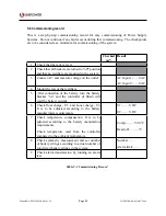
5.4 Commissioning procedure
1. Remove the alarm cover and check that all connections are made according to the
installation drawing. Verify that all connections are properly tightened with sufficient
torque.
2. Ensure that load and battery MCB breakers are set to OFF position - ensuring the load
and battery strings are connected.
3.
Ensure that all rectifier modules are removed. If not, remove each one in turn starting
from the rightmost position.
4. Check the battery polarity with the multimeter at the SB-50 connector. Place the positive
lead of the meter to the positive contact and the negative lead to the battery contact.
The meter must now show a positive voltage. If the voltage is negative, change over the
connection of the gray and black battery cables to the batteries.
5. Plug in the AC power cord.
6.
Plug in the rectifier modules, starting from the leftmost position. Make sure to fasten the
rectifiers again. The rectifiers will turn on automatically. Empty rectifier positions must
be cover with rectifier blanks.
7. Set all load breakers into the “1” (ON) position.
8. The green LED on the controller should blink for approximately 20 sec.
9.
The output voltage will increase slowly to U1 (float charge voltage).
10. Turn the battery breaker to the “1” (ON) position.
11. If any alarms are present, they should be reset in accordance with the procedure for the
installed controller, ACC Extended (ACX) or PCC.
12. The system should now be without alarms.
13. Attach all the system covers in their correct places.
14. Check that all changes to drawings, if any, have been completed.
15. Clean the site.
16. Fill in the commissioning record (table 5-2 in section 5.8).


