background image

PART III: OPERATION

41

    
ADJUSTING THE GAS VALVES GROUP

Multibloc MB-DLE

MultiBloc MBE


Regulation VD-R whith PS

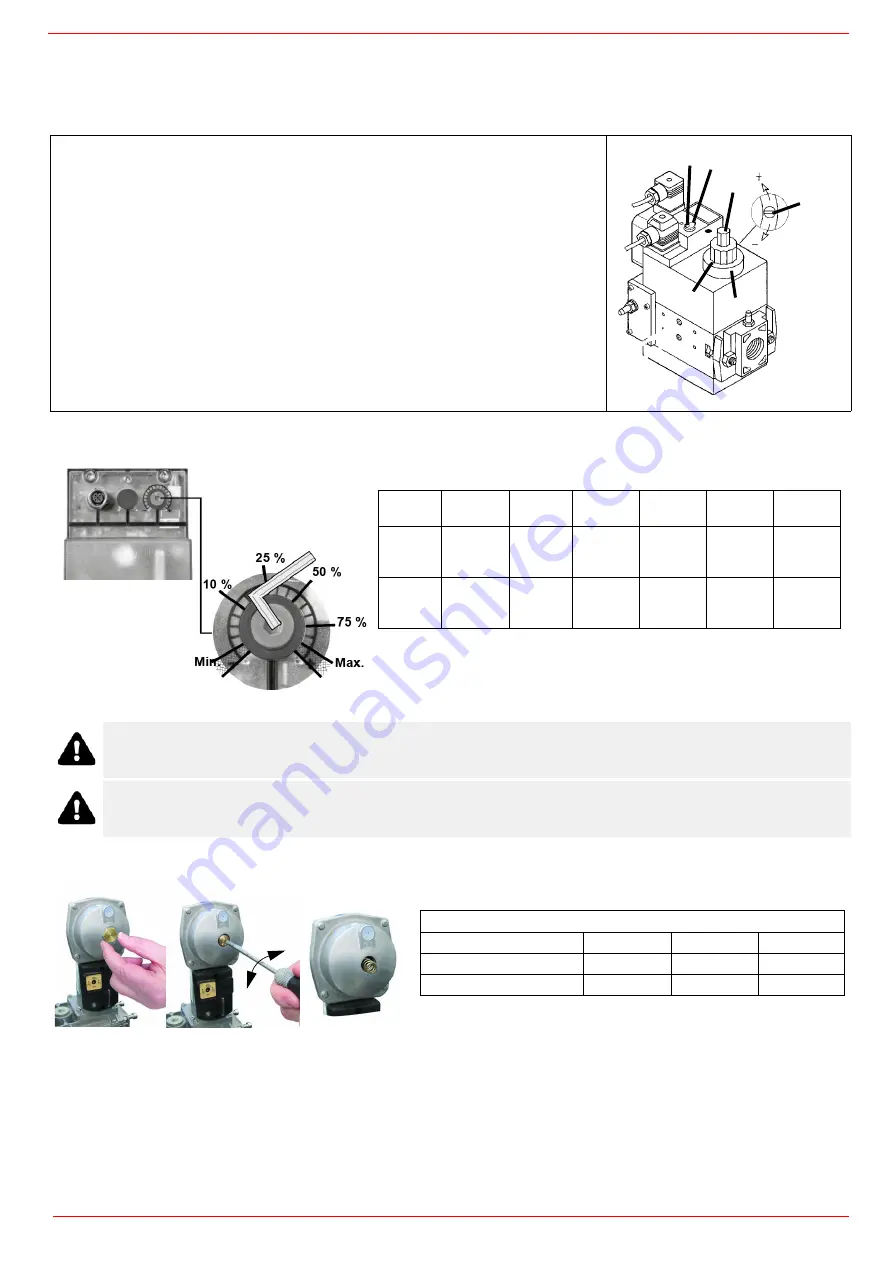
Siemens VGD../VRD.. version with SKP2 

The pressure adjusting range, upstream the gas valves group, changes according to the spring provided with the valve group.
To replace the spring supplied with the valve group, proceed as follows:i

To increase or decrease gas pressure, and therefore gas flow rate, remove the cap 

T

 and use a screwdriver to adjust the regulating

screw 

VR

. Turn clockwise to increase the flow rate, counterclockwise to reduce it.

The multibloc unit is a compact unit consisting of two valves, gas pressure switch, pressure
stabilizer and gas filter.
The valve is adjusted by means of the 

RP

 regulator after slackening the locking screw 

VB

 by

a number of turns. By unscrewing the regulator 

RP

 the valve opens, screwing the valve clo-

ses. To set the fast opening remove cover 

T

, reverse it upside down and use it as a tool to

rotate screw 

VR

. Clockwise rotation reduces start flow rate, anticlockwise rotation increases

it.
Do not use a screwdriver on the screw 

VR

!

The pressure stabilizer is adjusted by operating the screw 

VS

 located under the cover 

C

. By

screwing down the pressure is increased and by unscrewing it is reduced.
Note: the screw 

VSB

 must be removed only in case of replacemente of the coil.

Caution:

 check that the range of the installed spring is compatible with the gas pressure at the burner head (see 

appropriate diagram) to which must be added the back pressure and approx. 5 /10 mbar for various leaks and gas line.

While making outlet pressure adjustments, do not exceed a value that creates a hazardous condition to the bur-

ner!

C VS

T(

V

R

V

VSB

Outlet 

pressure

MIN

10%

25%

50%

75%

MAX

PS-10/40

4 mbar

0,4 kPa

2 "w.c.

10 mbar

1,0 kPa

4 "w.c.

25 mbar

2,5 kPa

10 "w.c.

50 mbar

5,0 kPa

20 "w.c.

75 mbar

7,5 kPa

30 "w.c.

100 mbar

10,0 kPa

40 "w.c.

PS-50/200

20 mbar

2,0 kPa

8 "w.c.

50 mbar

5,0 kPa

20 "w.c.

125 mbar

12,5 kPa

50 "w.c.

250 mbar

25,0 kPa

100 "w.c.

375 mbar

37,5 kPa

150 "w.c.

500 mbar

50,0 kPa

200 "w.c.

T

VR

Performance range (mbar)

neutral

yellow

red

Spring colour SKP 25.0

0 ÷ 22

15 ÷ 120

100 ÷ 250

Spring colour SKP 25.4

7 ÷ 700

150 ÷ 1500

+

-

Summary of Contents for N880X-FGR

Page 1: ...39578ZB 0 0 11 2022 BURNERS BRUCIATORI BRULERS BRENNER QUEMADORES ГОРЕЛКИ Microprocessor controlled MANUAL OF INSTALLATION USE MAINTENANCE LAMTEC BT3xx Gas Light oil burners N880X FGR N925X FGR N1060X FGR ...

Page 2: ... non original components whether spare parts kits accessories and optionals Force majeure Furthermore the manufacturer declines all responsibility for non compliance with this manual Personnel training The user is the person organisation or company that has acquired the appliance and intends to use it for the specific purpose The user is responsible for the appliance and for training the personnel...

Page 3: ...urner shut down reser the control box by means of the RESET pushbutton If a second shut down takes place call the Tech nical Service without trying to RESET further The unit shall be operated and serviced by qualified personnel only in compliance with the regulations in force GENERAL INSTRUCTIONS DEPENDING ON FUEL USED ELECTRICAL CONNECTION For safety reasons the unit must be efficiently earthed a...

Page 4: ...ty El Supply El Consump Fan Motor Protection Drwaing n P I N Do not touch any mechanical moving parts with your hands or any other part of your body Injury hazard Do not touch any parts containing fuel i e tank and pipes Scalding hazard Do not use the burner in situations other than the ones provi ded for in the data plate Do not use fuels other than the ones stated Do not use the burner in potent...

Page 5: ...of recirculation gas FGR Option 1 Damper with actuator Connect the actuator to the electrical predisposition inside the electrical panel Option 2 Damper manual Damper manual with Opening Closing signaling microswitches to be connected to the electrical predisposition inside the burner electrical panel Additional damper with actuator on chimney option 1 FGR ricirculate flue gas damper ...

Page 6: ... models for which a separate regulating valve is provided Other pumps are provided with two pressure regulators one for the high and one for low pressure in double stage systems with one nozzle The adjustable combustion head can improve the burner performance The combustion head determines the energetic quality and the geometry of the flame Fuel and comburent are routed into separated ways as far ...

Page 7: ...rter BRUCIATORE TIPO N880X FGR MG N925X FGR MG N1060X FGR MG Output min max kW 1500 7040 1300 7400 1550 8480 Fuel MG Natural gas Light oil Category see next paragraph Gas rate min max Stm3 h 159 745 138 783 164 897 Pressure mbar see Note 2 Light oil rate min max kg h 126 594 110 624 131 715 Oil viscosity cSt 40 C 2 7 4 2 7 4 2 7 4 Oil density kg m3 840 840 840 Oil train inlet pressure bar 2 max 2 ...

Page 8: ... 330 630 50 734 260 300 741 9 201 80 1970 2070 384 1307 722 35 562 841 132 445 545 648 1492 684 1950 1219 623 446 496 520 709 660 831 M16 651 460 460 460 944 204 740 1092 310 1161 448 330 630 50 734 260 300 741 9 201 100 1970 2070 384 1307 722 35 562 854 145 445 545 648 1492 684 1950 1235 623 446 496 520 709 660 831 M16 651 460 460 460 848 204 644 1092 350 1161 448 330 630 50 734 260 300 741 9 201...

Page 9: ... 1 Solenoid valve 10 Oil distributor 12 Pressure gauge 13 Pressure governor 15 Pressure switch 16 One way valve 16 1 One way valve 18 Flexible hose 19 Manual valve 20 Pressure gauge MAIN GAS TRAIN 23 Pressure switch PGMIN 24 Safety valve with built in gas governor 25 Proving system pressure switch PGCP 26 Pressure switch PGMAX 40 Manual valve 41 Bellows unit 42 Filter 44 Safety valve with built in...

Page 10: ...n range of the machine On this diagram the maximum output point is usually reached by adjsuting the combustion head to its MAX position see paragraph Adjusting the combustion head the minimum output point is reached setting the combustion head to its MIN position During the first ignition the combustion head is set in order to find a compromise between the burner output and the generator specifica...

Page 11: ... calorific value of 8125 kcal Stm3 15 C 1013 mbar and a density of 0 714 kg Stm3 The values in the diagrams refer to GPL with a calorific value of 22300 kcal Stm3 15 C 1013 mbar and a density of 2 14 kg Stm3 When the calorific value and the density change the pressure values should be adjusted accordingly Where Natural gas pressure shown in diagram Real gas pressure Natural gas flow rate shown in ...

Page 12: ... burner head vs natural gas flow rate Curves are referred to pressure 0 mbar in the combustion chamber Gas pressure in combustion head N880X M Gas rate Stm3 h N925X M Gas rate Stm3 h Gas pressure in combustion head N1060X M Gas rate Stm3 h ...

Page 13: ...lue as a function of the heat load of the boiler for that burner multiply the required burned power by the depowering factor expressed as follows multiply the back pressure in the combustion chamber by the depressurisation factor squared pressure losses vary with the square of the change in flow rate choose the burner considering the new power and back pressure value if the burner size is insuffic...

Page 14: ...PART I SPECIFICATIONS 14 Burner power reduction N1060X FGR Thermic Load MW m3 ...

Page 15: ... tube lenght consider the following rule even if it differs from the instructions of the boiler manufacturer Cast iron boilers three pass flue boilers with the first pass in the rear part the blast tube must protrude at least 150 200 mm into the combustion chamber The length of the blast tubes does not always allow this requirement to be met and thus it may be necessary to use a suitably sized spa...

Page 16: ...his stage the combustion head the gas butterfly valve and the actuator are at the maximum opening Refer to showing the correct way to measure the gas pressure considering the values o pressure in combustion chamber surveyed by means of the pressure gauge or taken from the boiler s Technical specifications Measuring gas pressure in the combustion head In order to measure the pressure in the combust...

Page 17: ... the stirrup only once the burner is installed to the boiler Packing The burners are despatched in wooden crates whose dimensions are 2234 X 1650 X H 1250 Packing cases of this type are affected by humidity and are not suitable for stacking The following are placed in each packing case burner with detached gas train gasket or ceramic fibre plait according to burner type to be inserted between the ...

Page 18: ...plant designed according to the following guidelines size the FGR pipe as per the example below ATTENTION Pipe elbows increase pressure losses so limit their use as much as possible Flue gas temperature 150 C or 150 273 15 423 15 K Ambient temperature 15 C or 15 273 15 288 15 K FGR flow for dimensioning 1 61 x 20 0 322 Stm3 s FGR flow corrected for flue gas temperature 0 322 x 423 15 288 15 0 473 ...

Page 19: ... the current laws Key Gas train with valves group VGD and MBE with built in gas pressure governor gas pressure switch PGMIN LT 1 Filter 6 Butterfly valve 8 Main burner 3 Safety valve with built in gas governor 9 Bellows unit optional 4 Pressure switch PGMIN LT 10 Manual valve optional 5 Pressure switch PGMAX included MBE for VGD e MB DLE Optional GAS INLET SUPPLIED BY BURNER CONSTRUCTOR BY OTHERS ...

Page 20: ...cording to the procedure set by laws in force CAUTION The direction of gas flow must follow the arrow on the body of the components mounted on the gas ramp valves filters gaskets NOTE the bellows unit the manual cutoff valve and the gaskets are not part of the standard supply first step install the flanges to prevent entry of foreign bodies in the gas line on the gas pipe clean the already assembl...

Page 21: ...o tube lines use appropriate sealing agent 2 Insert MB DLE note position of O rings 3 Remove MultiBloc between the threaded flanges 4 After installation perform leakage and functional test 5 Disassembly in reverse order A B C D A MOUNTING POSITIONS A B MB DLE 405 412 B C D MB DLE 415 420 O Ring ...

Page 22: ...pressure switch 4 PGMAX maximum gas pressure switch 5 Actuator with integrated pressure stabiliser 6 On Off actuator 7 Valve body Threaded 8 Valve body Flange On equipment versions Facile VD R must be installed upstream valve 3 5 1 2 4 6 8 VD R VD V 3 5 1 2 4 6 7 VD R VD V min 5 Ø Ø VD R VD V PS 1 2 3 4 Sealing plug G1 8 ISO 228 5 Locking screw For version VB 2L only connection for vent line NPT 1...

Page 23: ...h SKP2 built in pressure stabilizer Siemens VGD VRD SKPx5 Auxiliary optional micro switch Gas valve If the auxiliary microswitch POC is required a dedicated actuator different from the one usually supplied must be ordered The con nection is shown in the figure WARNING removing the four screws BS causes the device to be unserviceable 3 5 2 1 4 6 6 8 SKP15 SKP25 SKP15 SKP25 5 2 1 3 4 7 1 PGMIN minim...

Page 24: ... 24 Siemens VGD Pressure taps G 1 4 G 1 8 G 1 4 G 3 4 G 1 8 G 1 4 G 1 8 Strainer 1 9 3 4 5 2 11 7 6 8 2 V 1 V 10 1 2 4 3 9 1 6 10 3 2 11 10 5 6 7 8 9 Legend pi Inlet pressure pm Pressure between val ves po Outlet pressure ...

Page 25: ...m tank To tank The burner is supplied with filter and flexible hoses all the parts upstream the filter and downstream the return flexible hose must be installed by the customer As far as the hoses connection see the related paragraph Key 1 Burner 2 Flexible hoses fitted 3 Light oil filter fitted 4 Automatic interceptor 5 One way valve 6 Gate valve 7 Quick closing gate valve outside the tank or boi...

Page 26: ...tank this installation can be considered self ble eding If provided the inside by pass plug must be installed to avoid air and fuel passing through the pump Burners come out from the factory provided for double pipe systems They can be suited for single pipe system recommended in the case of gravity feed as decribed before To change from a 1 pipe system to a 2 pipe system insert the by pass plug G...

Page 27: ...ssible source of leakage Do not use PTFE tape on the suction and return line pipes to avoid the possibility that particles enter circulation These could depo sit on the pump filter or the nozzle reducing efficiency Always use O Rings or mechanical seal copper or aluminium gaskets jun ctions if possible An external filter should always be installed in the suction line upstream the fuel unit 1 Conne...

Page 28: ...oses on the pump being careful to avoid exchanging the lines see the arrows marked on the pump For further information refer to the technical documentation of the pump Suntec T Viscosity 3 75 cSt Oil temperature 0 150 C Minimum suction pressure 0 45bar to prevent gasing Maximum suction pressure 5 bar Rated speed 3600 rpm max Key 1 Inlet G3 4 2 Pressure gauge port G1 4 3 Vacuum gauge port to measur...

Page 29: ...ling recommendations avaible on the Siemens CD attached to the burner WARNING Respect the basic safety rules make sure of the connection to the earthing system do not reverse the phase and neutral connections fit a differential thermal magnet switch adequate for connection to the mains WARNING before executing the electrical connections pay attention to turn the plant s switch to OFF and be sure t...

Page 30: ...ING WITH THESE E G DISCONNECTION EVEN PARTIAL OF THE ELECTRICAL LEADS OPENING THE GENERATOR DOOR DISMANTLING OF PART OF THE BURNER NEVER OPEN OR DISMANTLE ANY COMPONENT OF THE MACHINE EXCEPT FOR ITS MAINTENANCE TO SECURE THE MACHINE ACT ON THE ISOLATOR SWITCH IN CASE OF ANOMALIES THAT REQUIRED A SHUT DOWN OF THE BURNER IT S POSSIBLE TO ACT ON THE AUXILIARY LINE SWITCH LOCATED ON THE BURNER FRONT P...

Page 31: ...flame operation LED B3 Lo flame operation LED B4 Ignition transformer operation LED B5 Fan motor overload tripped LED B6 Stand by signalling lamp G1 Gas valves EV2 operation signalling lamp G2 Gas valves EV1 operation signalling lamp G3 Gas pressure switch signal lamp G4 Gas proving system lockout signalling lamp O5 Oil valve EVG operation signalling lamp P1 Pilot gas pressure switch consent opera...

Page 32: ...former is energised signalled by the light H on the front panel then few seconds later the EV1 and EV2 gas valves are energised light L and I on the front panel Few seconds after the gas valves opening the ignition transformer is de energised and light H turns to off The burner operates in the low flame stage few seconds later the two stages operation begins and the burner output increases or decr...

Page 33: ...s present and stable closes the contact giving consent to the equipment to continue the starting cycle When the burner is switched off due to the intervention of the thermostat boiler pressure switch the BT3xx keeps the EV2 gas valve open to allow the pressure between the gas valves to be released and the PGMIN LT pressure switch contact to rest and ready to restart the burner AIR FLOW AND FUEL AD...

Page 34: ... home page keep thermostat open Burner remain in stand by Unlock the controller press ENTER Info Press the right key to position on the Settings icon indicated with wrench and hammer Press ENTER Manual Setting Press ENTER again after selecting the key icon ...

Page 35: ...t click to EDIT Press ENTER to enter the curves page Keep the password 0000 and confirm with ENTER Air gas position at burner s ignition 1 ignition position 2 air servomotor position digit 1 gas servomotor position digit VALUES VARY FROM BURNER TO BURNER ...

Page 36: ...oes not start with those settings the chap ter SETTING THE IGNITION POINT WITH BURNER IN STAND BY In case of troubles the burner will go on lock out mode and the reason will be indicated on the display The controller moves the servomotors to the ignition position and excites the ignition transformer SETTING THE IGNITION POINT WITH BURNER IN STAND BY ...

Page 37: ... the lock code press ENTER to unlock Press ENTER to modify the positions burner in stand by Click up to increase the gas opening position or down to decrease it Clickup to increase the air opening position or down to decrease it ...

Page 38: ...o modify the combustion valves and adjust servomo tors position gas and air press ENTER Click up to increase the gas opening position or down to decrease it Right click to move from gas servomotor adjustment to air servomotor adjustment Click up to increase the air opening position or down to decrease it BURNER OPERATING SETTING PARAMETERS ...

Page 39: ... BURNER IN STAND BY Set the maximum load position 999 according to the maximum output required by the boiler If necessary set the inlet gas pressure at the exit of the gas pres sure reducer Check the output combustible and the quality of combustion in all positions and adjust gas and air if necessary see chapter SETTING THE IGNITION POINT WITH BURNER IN STAND BY Press EXIT to quit the combustion s...

Page 40: ...re CAUTION The fuel air calibration procedure is the same for both gas and diesel In the display will be indicated Gas or Diesel Press EXIT again to quit main menu Press EXIT again to quit settings The burner runs now in automatic mode In case of troubles the burner will go on lock out mode and thereason will be indicated on the display Exemple H009 lock out code D1 diagnostic 1 D2 diagnostic 2 xx...

Page 41: ...ion reduces start flow rate anticlockwise rotation increases it Do not use a screwdriver on the screw VR The pressure stabilizer is adjusted by operating the screw VS located under the cover C By screwing down the pressure is increased and by unscrewing it is reduced Note the screw VSB must be removed only in case of replacemente of the coil Caution check that the range of the installed spring is ...

Page 42: ... the minimum gas pressure switch Slowly close the manual cutoff valve placed upstream the pressure switch see gas train installation diagram until the detected pressure is reduced by 50 Pay attention that the CO value in the flue gas does not increase if the CO values are higher than the limits laid down by law slowly open the cutoff valve as to get values lower than these limits Check that the bu...

Page 43: ...bustion head backwards turning clockwise the knob VRT Fasten VB screw when the adjustment is accomplished Depending on the boiler application it is possible to act on the holes figure B to improve the flame stability and NOx CO emission values If necessary close open the holes in figure B using the screws kit given with the burner Attention if it is necessary to change the head position repeat the...

Page 44: ...ON To achieve the maximum flow rate close completely the return line DIMENSIONS FLOW RATE kg h Indicative pessure on return bar Min Max 40 13 40 19 50 16 50 22 60 20 60 20 70 23 70 23 80 26 80 23 90 30 90 22 100 33 100 22 115 38 115 21 130 43 130 22 145 48 145 21 160 53 160 21 180 59 180 22 200 66 200 21 225 74 225 22 250 82 250 22 275 91 275 22 300 99 300 23 330 109 330 23 360 119 360 22 400 132 ...

Page 45: ...PART III OPERATION 45 NOZZLE SUPPLY PRESSURE 20 bar VISCOSITY AT NOZZLE 5 cSt Pressure on return bar Flow rate kg h The nominal size of the nozzle is indicated at the ends of the curve ...

Page 46: ...PRESSURE 20 bar VISCOSITY AT NOZZLE 5 cS Pressure on return bar Flow rate kg h Pressure on return bar Flow rate kg h The nominal size of the nozzle is indicated at the ends of the curve The nominal size of the nozzle is indicated at the ends of the curve ...

Page 47: ...return bar Flow rate kg h The nominal size of the nozzle is indicated at the ends of the curve Pressure on return bar Flow rate kg h The nominal size of the nozzle is indicated at the ends of the curve Pressure on return bar Flow rate kg h The nominal size of the nozzle is indicated at the ends of the curve ...

Page 48: ...atio curve see the LMV related manual 5 Only if necessary adjust the supply pressure as follows see related paragraph insert a pressure gauge into the port shown on Fig 5 and act on on the pump adjusting screw VR see Fig 4 as to get the nozzle pressure at 20bar Monarch or Fluidics nozzles see page 44 38 6 In order to get the maximum oil flow rate adjust the pressure reading its value on the PG pre...

Page 49: ...re change on the return line could affect the combustion parameters for this reason the pressure switch must be set say at 20 over the pressure recorded during the combustion adjustment The factory setting is 4 bar It is recommended to verify that the combustion parameters are within the range of acceptable values even against a pressure varia tion that gets close to the limit of the pressure swit...

Page 50: ...be damaged it must be replaced remove check and clean the combustion head check the ignition electrodes and their ceramic insulators clean adjust and replace if necessary remove and clean the oil nozzles IMPORTANT do not clean the nozzles using metallic or sharp utensils use only solvents or steam at the end of maintenance operations refit the burner turn it on and check the combustion If in doubt...

Page 51: ...ed to the last check You can change the filter without removing the fitting 1 Interrupt the gas supply closing the on off valve 2 Remove screws 1 4 using the Allen key n 3 and remove filter cover 5 in Fig 5 3 Remove the filter 6 and replace with a new one 4 Replace filter cover 5 and tighten screws 1 4 without using any force and fasten 5 Perform leakage and functional test pmax 360 mbar Bouchon à...

Page 52: ... to push 1 2 3 4 5 6 7 1 Position VD on VB fig 2 3 2 Slide VD forward up to the stop fig 4 3 Screw VD on with 2 M5 screws for each max 5 Nm 44 in lb fig 5 6 4 VD can be mounted rotated by 180 fig 7 VB VD SKP15 001 SKP25 003 AIR To replace the actuators turn the screws as shown in the drawing ...

Page 53: ...o any electrical equipmente on the filter Removing the combustion head 1 Remove the top H 2 Remove the UV detector out of its housing disconnect electrode cables and the light oil flexible hoses 3 Loosen the screws V holding the gas manifold G loosen the connectors E 4 Some models are provided with the T baffle Move the gas manifold ahead and remove the baffle 5 Pull out the complete group as show...

Page 54: ...etallic parts blast tube head etc otherwise the boiler operation would be compromised Check the electrodes position after any intervention on the combustion head To replace the ignition electrodes proceed as follows 1 remove the burner cover 2 loose the nuts that fasten the electrodes group to the combustion head A 3 disconnect the electrodes cables B 4 loose the security dowes of the adjusting ri...

Page 55: ...ording to the quotes shown othe next picture Minimum detection signal 3 5Vdc Fig 7 Detection with detector QRI ATTENTION avoid the ignition and detection electrodes to contact metallic parts blast tube head etc other wise the boiler s operation would be compromised Check the electrodes position after any intervention on the combustion head D B A C 8 10 3 37 A mm B 8 mm C mm D 5 mm A ...

Page 56: ...gnosis and if necessary an overall repair The burner status is considered to be at its limit if it is technically impossible to continue using it due to non compliance with safety requirements or a decrease in performance The owner makes the decision whether to finish using the burner or replacing and disposing of it based on the actual state of the appliance and any repair costs The use of the bu...

Page 57: ... Check air pressure switch functions and links Burner control damaged Replace burner control BURNER LOCKS OUT WITHOUT ANY GAS FLOW Gas valves don t open Check voltage on valves if necessary replace valve or the burner control Check if the gas pressure is so high that the valve cannot open Gas valves completely closed Open valves Pressure governor too closed Adjust the pressure governor Butterfly v...

Page 58: ...nition transformer or into the electrodes Improve the installation Ignition transformer damaged Replace the transformer PUMP TOO NOISY Suction too high over 0 35 bar dirty filters check valve in the tank locked and so on Clean filters Replace check valve in the tank Flexible hoses damaged Replace flexible hoses Air infiltration in the pipes Take off all infiltration Pipe too long or too narrow Inc...

Page 59: ......

Page 60: ...ia L Galvani 9 35011 Campodarsego PD ITALY Tel 39 049 9200944 Fax 39 049 9200945 9201269 web site www cibunigas it e mail cibunigas cibunigas it Note specifications and data subject to change Errors and omissions excepted ...

Reviews: