background image

4

-EN 60204-1:2006 (Safety of machinery – Electrical equipment of machi-
nes.)
-CEI EN 60335-1 (Specification for safety of household and similar electri-
cal appliances);
-CEI EN 60335-2-102 (Household  and  similar electrical appliances.
Safety. Particular requirements for gas, oil and solid-fuel burning applian-
ces having electrical connections).
-UNI EN ISO 12100:2010 (Safety of machinery - General principles for
design  - Risk assessment and risk reduction);

Norme nazionali / National Standard

-UNI 7824 (Atomizing burners of the monobloc type. Characteristics and
test methods.

Gas - Heavy oil burners

European directives:

-2009/142/EC (Gas Directive)
-2014/35/UE (Low Tension Directive)
-2014/30/UE (Electromagnetic compatibility Directive)
-2006/42/EC  (Machinery Directive)

Harmonized standards

-UNI EN 676  (Automatic forced draught burners for gaseous fuels)
-EN 55014-1 (Electromagnetic compatibility- Requirements for house
hold appliances, electric tools and similar apparatus)
-EN 60204-1:2006 (Safety of machinery – Electrical equipment of machi-
nes.)
-CEI EN 60335-1 (Specification for safety of household and similar electri-
cal appliances);
-CEI EN 60335-2-102 (Household  and  similar electrical appliances.
Safety. Particular requirements for gas, oil and solid-fuel burning applian-
ces having electrical connections).
-UNI EN ISO 12100:2010 (Safety of machinery - General principles for
design  - Risk assessment and risk reduction);

National Standard

- UNI 7824 (Atomizing burners of the monobloc type. Characteristics and 
test methods.

Industrial burners

European directives

-2009/142/EC (Gas Directive)
-2014/35/UE (Low Tension Directive)
-2014/30/UE (Electromagnetic compatibility Directive)
-2006/42/EC  (Machinery Directive)

Harmonized standards

-EN 55014-1 (Electromagnetic compatibility- Requirements for house
hold appliances, electric tools and similar apparatus)
-EN 746-2 (Industrial thermoprocessing equipment - Part 2: Safety requi-
rements for combustion and fuel handling systems)
-UNI EN ISO 12100:2010 (Safety of machinery - General principles for
design  - Risk assessment and risk reduction);
-EN 60204-1:2006 (Safety of machinery – Electrical equipment of machi-
nes.)
-EN 60335-2 (Electrical  equipment  of non-electric appliances for house-
hold and similar purposes. Safety requirements)
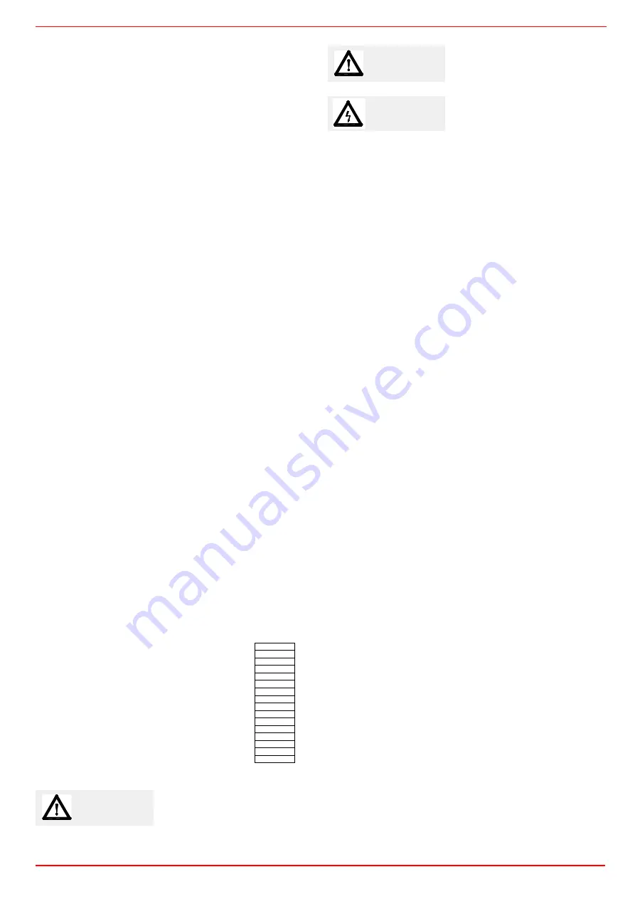
Burner data plate

For the following information, please refer to
the data plate:

z

burner type and burner model: must be
reported in any communication with the
supplier

z

burner ID  (serial number): must be repor-
ted in any communication with the supplier

z

date of production (year and month)

z

information about fuel type and network
pressure

SYMBOLS USED

Figures, illustrations and images used in this manual may differ in appearance from

the actual product.

WARNING!

Failure to observe the warning may
result in irreparable damage to the
unit or damage to the environment

Type --
Model

--

Year --
S.Number --
Output --
Oil Flow 

--

Fuel

--

Category --
Gas Pressure 

--

Viscosity --
El.Supply --
El.Consump. --
Fan Motor 

--

Protection --
Drwaing n° 

--

P.I.N.

--

DANGER!

Failure to observe the warning may
result in serious injuries or death.

WARNING!

Failure to observe the warning may
result in electric shock with lethal con-
sequences

Summary of Contents for HR75A MG Series

Page 1: ...M039327CA Rel 1 0 10 2020 BURNERS BRUCIATORI BRULERS BRENNER QUEMADORES ГОРЕЛКИ Gas light oil burners MANUAL OF INSTALLATION USE MAINTENANCE HR75A ...

Page 2: ...in a suitable room with ventilation openings complying with the requirements of the regulations in force and sufficient for good combustion z Only burners designed according to the regulations in force should be used z This burner should be employed exclusively for the use for which it was designed z Before connecting the burner make sure that the unit rating is the same as delivery mains electric...

Page 3: ... EC Gas Directive 2014 35 UE Low Tension Directive 2014 30 UE Electromagnetic compatibility Directive 2006 42 EC Machinery Directive Harmonized standards UNI EN 676 Automatic forced draught burners for gaseous fuels EN 55014 1 Electromagnetic compatibility Requirements for house hold appliances electric tools and similar apparatus EN 60204 1 2006 Safety of machinery Electrical equipment of machi n...

Page 4: ...type Characteristics and test methods Industrial burners European directives 2009 142 EC Gas Directive 2014 35 UE Low Tension Directive 2014 30 UE Electromagnetic compatibility Directive 2006 42 EC Machinery Directive Harmonized standards EN 55014 1 Electromagnetic compatibility Requirements for house hold appliances electric tools and similar apparatus EN 746 2 Industrial thermoprocessing equipme...

Page 5: ...n fuel and air to perform clean and efficient combustion is activated by atomisation of oil into very small particles This process is achieved making pressurised oil passing through the nozzle The pump main function is to transfer oil from the tank to the nozzle in the desired quantity and pressure To adjust this pressure pumps are provided with a pressure regulator except for some models for whic...

Page 6: ...ght oil B Biogas 3 OPERATION Available versions PR Progressive MD Fully modulating AB Double stage 4 BLAST TUBE S Standard 5 DESTINATION COUNTRY see data plate 6 BURNER VERSION A Standard Y SpecialeSpecial 7 EQUIPMENT 1 2 gas valves gas proving system 8 2 gas valves gas proving system maximum gas pressure switch 8 GAS CONNECTION 40 Rp11 2 50 Rp2 65 DN65 80 DN80 Fuel Hi KWh Stm3 ρ kg Stm3 fQ fp Tow...

Page 7: ...Siemens VGD Minimum gas pressure see gas curves Note3 Burners are suitable only for indoor operation with a maximum relative humidity of 80 NOTE ON THE WORKING SERVICE the control box automatically stops after 24h of continuous working The control box immediately starts up automatically Country and usefulness gas categories GAS CATEGORY COUNTRY I2H AT ES GR SE FI IE HU IS NO CZ DK GB IT PT CY EE L...

Page 8: ...5A PR MD 1 50 1506 69 553 435 28 305 503 374 1002 352 979 618 361 254 270 235 300 503 M10 216 250 233 465 127 338 525 658 218 155 1 65 1506 69 553 435 28 305 503 374 1002 352 1051 690 361 254 270 282 300 503 M10 216 250 233 535 127 408 565 292 658 218 155 1 80 1506 69 553 435 28 305 503 374 1002 352 1051 690 361 254 270 284 300 503 M10 216 250 233 555 127 428 565 310 658 218 155 BB CC Z L AE U E D...

Page 9: ...ributor 11 Flexible hose 12 Pressure gauge 13 Pressure governor 15 Pressure switch 16 One way valve 16 1 One way valve 17 Flexible hose 18 Flexible hose 19 Manual valve 20 Pressure gauge MAIN GAS TRAIN 40 Manual valve 41 Bellows unit 42 Filter 43 Pressure switch PGMIN 44 Safety valve with built in gas governor 45 Proving system pressure switch PGCP 46 Pressure switch PGMAX 47 Butterfly valve COMBU...

Page 10: ... valve 7 Flexible hose 10 Oil distributor 11 Flexible hose 12 Pressure gauge 13 Pressure governor 15 Pressure switch 16 One way valve 16 1 One way valve 17 Flexible hose 18 Flexible hose 19 Manual valve 20 Pressure gauge 21 Solenoid valve MAIN GAS TRAIN 27 Proving system 40 Manual valve 41 Bellows unit 42 Filter 43 Pressure switch PGMIN 44 Safety valve with built in gas governor 46 Pressure switch...

Page 11: ...mum output point is rea ched setting the combustion head to its MIN position During the first ignition the combustion head is set in order to find a compromise between the burner output and the generator specifications that is why the minimum output may be different from the Per formance curve minimum Checking the proper gas train size PRESSURE IN COMBUSTION CHAMBER mbar HR75A kW To check the prop...

Page 12: ...w the minimum pressure at the gas train inlet necessary to get the requested gas rate add the pressure value in the combustion chamber to the value read on the y axis GAS PRESSURE IN THE NETWORK mbar HR75A L Gas rate Stm3 h Caution the gas rate value is quoted on the x axis the related network pressure is quoted on the y axis pressure value in the combustion chamber is not included To know the min...

Page 13: ... the combustion chamber 3 Gas pressure outlet on the butterfly valve 4 Differential pressure gauge Measuring the gas pressure in the combustion head In order to measure the pressure in the combustion head insert the pressure gauge probes one into the combustion chamber s pressure outlet to get the pressure in the combustion chamber and the other one into the butterfly valve s pressure outlet of th...

Page 14: ... Pressure rate in combustion head curves LPG Curves are referred to pressure 0 mbar in the combustion chamber Gas pressure in combustion head mbar HR75A M Stm3 h Curves are referred to pressure 0mbar in the combustion chamber Gas pressure in combustion head mbar HR75A L Stm3 h ...

Page 15: ...ety regulations Do not stand under lifted loads Packing The burners are despatched in wooden crates whose dimensions are 1672mm x 1072mm x 1016mm L x P x H Packing cases of this type are affected by humidity and are not suitable for stacking The following are placed in each packing case z burner with detached gas train z gasket or ceramic fibre plait according to burner type to be inserted between...

Page 16: ...t the supplier to verify that a correct matching is possible with respect of the application involved To correctly match the burner to the boiler verify the type of the blast tube Verify the necessary input and the pressure in combustion chamber are included in the burner performance curve otherwise the choice of the burner must be revised consulting the burner manufacturer To choose the blast tub...

Page 17: ...next paragraphs according to the gas train used z threaded gas trains with Multibloc Dungs MB DLE or Siemens VGD20 z flanged gas trains with Siemens VGD40 WARNING BEFORE EXECUTING THE CONNECTIONS TO THE GAS PIPE NETWORK BE SURE THAT THE MANUAL CUTOFF VALVES ARE CLOSED ATTENTION once the gas train is mounted according to the diagram on Fig 5 the gas proving test mus be per formed according to the p...

Page 18: ...re fitted z Connect the reference gas pipe TP in figure 8mm external size pipe supplied loose to the gas pressure nipples placed on the gas pipe downstream the gas valves gas pressure must be measured at a distance that must be at least 5 times the pipe size Leave the blowhole free SA in figure Should the spring fitted not permit satisfactory regulation ask one of our service centres for a suitabl...

Page 19: ...ner side opens and keep this position for a preset time td4 in order the bring the test space to ambient pressure Test atmospheric pressure EV1 closes and keep this position for a preset time test time td1 The pressure switch PGCP has not to detect a rise of pressure z Test space filling EV2 opens and keep this position for a preset time td3 in order to fill the test space z Test gas pressure EV2 ...

Page 20: ... circuits NOTE in plants where gravity or ring feed systems are provided install an automatic interception device Fig 15 Gravity circuit Fig 16 Ring circuit Fig 17 Suction circuit Key 1 Manual valve 2 Light oil filter 3 Light oil feeding pump 4 One way valve 5 Flexible hoses 6 Relief valve ...

Page 21: ...to avoid air and fuel passing through the pump Burners come out from the factory provided for double pipe systems They can be suited for single pipe system recommended in the case of gravity feed as decribed before To change from a 1 pipe system to a 2 pipe system insert the by pass plug G as for ccw rota tion referring to the pump shaft Caution Changing the direction of rotation all connections o...

Page 22: ...hese could depo sit on the pump filter or the nozzle reducing efficiency Always use O Rings or mechanical seal copper or aluminium gaskets jun ctions if possible z An external filter should always be installed in the suction line upstream the fuel unit Key 1 Pressure governor 2 Pump pressure gauge 3 Vacuum gauge 5 To the nozzle 7 Inlet 8 Return 1 Inlet G1 2 2 To the nozzle G1 2 3 Return G1 2 4 Pre...

Page 23: ...ting the oil flexible hoses to the pump To connect the flexible oil hoses to the pump proceed as follows according to the pump provided 1 remove the closing nuts A and R on the inlet and return connections of the pump 2 screw the rotating nut of the two flexible hoses on the pump being careful to avoid exchanging the lines see the arrows marked on the pump For further information refer to the tech...

Page 24: ...inal X3 04 4 in case of LMV2x LMV3x LMV5x LME7x on the board and the earth terminal an RC Siemens RC466890660 filter must be inserted For LMV5 control box please refer to the clabeling recommendations avaible on the Siemens CD attached to the burner WARNING Respect the basic safety rules make sure of the connection to the earthing system do not reverse the phase and neutral connections fit a diffe...

Page 25: ...VER OPEN OR DISMANTLE ANY COMPONENT OF THE MACHINE EXCEPT FOR ITS MAINTENANCE TO SECURE THE MACHINE ACT ON THE ISOLATOR SWITCH IN CASE OF ANOMALIES THAT REQUIRED A SHUT DOWN OF THE BURNER IT S POSSIBLE TO ACT ON THE AUXILIARY LINE SWITCH LOCATED ON THE BURNER FRONT PANEL IN CASE OF A BURNER SHUT DOWN RESET THE CONTROL BOX BY MEANS OF THE RESET PUSHBUTTON IF A SECOND SHUT DOWN TAKES PLACE CALL THE ...

Page 26: ... EV1 opening LED G3 Gas pressure switch signal LED S1 Main switch S2 Reset pushbutton for control box S3 Operation selector MAN AUTO operation in manual or automatic mode MIN operation with minimum output 0 Stop MAX operation at the maximum output S4 Fuel selection O1 EVG1 solenoid valve operation LED O2 EVG2 solenoid valve operation LED O3 Pump motor overload tripped LED O4 Oil pump in operation ...

Page 27: ...tor overload tripped LED G1 EV2 opening LED G2 EV1 opening LED G3 Gas pressure switch signal LED S1 Main switch S2 Reset pushbutton for control box S4 Fuel selection O1 EVG1 solenoid valve operation LED O2 EVG2 solenoid valve operation LED O3 Pump motor overload tripped LED O4 Oil pump in operation LED O5 EVG3 solenoid valve operation LED I S1 B1 S2 B2 B3 B4 B5 G1 G2 G3 S4 O1 O2 O3 O4 O5 ...

Page 28: ... transformer turns on signalled by the lamp B4 and few seconds later the solenoid valves EV1 and EV2 are energized lights G1 and G2 on the front panel z Few seconds after the opening of the valves the ignition transformer turns off and the lamp B4 turns off subsequently Double stage burners the burner is on in low flame stage light G is on some seconds later the high flame operation begins and the...

Page 29: ...s temperature gets too low to cause condensation in the chimney To change the burner setting during the testing in the plant follows the next procedure according to the model provided Adjusting the combustion head The burner is factory adjusted with the combustion head in the MAX position accordingly to the maximum power To operate the bur ner at a lower power progressively shift back the combusti...

Page 30: ...hich the burner is designed z For natural gas burners plate holes are fully opened HR75A L Center head holes gas flow regulation To adjust the gas flow partially close the holes as follows 1 loosen the three V screws that fix the adjusting plate D 2 insert a screwdriver on the adjusting plate notches and let it move CW CCW as to open close the holes 3 once the adjustmet is performed fasten the V s...

Page 31: ... after slackening the locking screw VB by a number of turns By unscrewing the regulator RP the valve opens screwing the valve closes The pressure stabilizer is adjusted by operating the screw VS located under the cover C By screwing down the pressure is increased and by unscrewing it is reduced Note the screw VSB must be removed only in case of replacemente of the coil Siemens VGD valves group rem...

Page 32: ...on cam position that is why it must be set at about 30 more than the ignition cam 13 Turn the burner off and then start it up again If the adjustment is not correct repeat the previous steps z Berger STA on this actuator the manual control of the air damper is not provided the setting of the cams is carried out working with a screwdriver on the VS screw placed on the cam z Berger STA12 a key is pr...

Page 33: ...ow flame cam the low flame position matches the ignition position As far as burners fitted with Dungs MBC gas valves the low flame cam does not match the ignition cam position that is why it must be set at about 30 more than the ignition cam 15 Turn the burner off and then start it up again If the adjustment is not correct repeat the previous steps Fully modulating burners To adjust the fully modu...

Page 34: ...ing down the pressure is increased and by unscrewing it is reduced Note the screw VSB must be removed only in case of replacemente of the coil Fig 19 Fig 20 Key 1 Electrical connection for valves 2 Operation display optional 3 Pressure governor closing tap 4 Start setting cap 5 Hydraulic brake and rate regulator 6 Coil 7 Test point connection G 1 8 8 Test point connection G 1 8 downstream of valve...

Page 35: ...witch is mounted downstream the gas governor gas valves group and upstream the butterfly valve light the burner adjust it according to the procedure in the previous paragrph Then measure the gas pressure at the operating flow rate downstream the gas governor gas valves group and upstream the butterfly valve by means of the adjusting ring nut VR set the value read on step 2 increased by the 30 4 re...

Page 36: ...0 12 8 4 5 9 2 9 4 10 0 11 0 11 9 12 9 14 3 15 3 17 2 24 5 24 8 14 1 5 0 10 8 11 0 11 3 11 6 13 0 14 3 15 6 17 0 18 6 24 3 26 2 13 4 5 5 9 7 10 0 10 2 11 1 12 1 13 4 14 8 16 4 18 1 29 7 12 4 6 0 9 2 9 5 9 9 10 0 10 8 12 4 14 1 15 7 17 5 18 9 29 3 33 1 14 8 6 5 10 5 10 8 11 1 11 4 12 1 13 8 15 3 16 5 18 4 20 0 22 4 36 2 36 7 15 5 7 0 8 7 9 4 10 0 11 4 13 2 14 9 17 2 19 6 23 1 25 1 33 2 33 7 15 2 7 ...

Page 37: ...et the return pressure at 11bar supply at 20bar on the delivery to get a 220kg h flow rate If the return pressure needed is 5bar instead act on the V adjusting screw on the pressure governor see chapter on page 36 The flow rate will then be about 95kg h see the example showed on the Bergonzo diagram ...

Page 38: ...PART III OPERATION 38 Fig 22 ...

Page 39: ...is provided set the return pressure at 13bar supply at 20bar on the delivery to get a 110kg h flow rate If the return pressure needed is 5bar instead act on the adjusting screw on the pressure gover nor The flow rate will then be about 55kg h see the example showed on the Bergonzo diagram ...

Page 40: ...PART III OPERATION 40 FLUIDICS KW3 60 NOZZLE SUPPLY PRESSURE 20 bar VISCOSITY AT NOZZLE 5 cSt Pressure on return bar Flow rate kh h The nominal size of the nozzle is indicated at the ends of the curve ...

Page 41: ...RESSURE 20 bar VISCOSITY AT NOZZLE 5 cSt Pressure on return bar Flow rate kh h Pressure on return bar Flow rate kh h The nominal size of the nozzle is indicated at the ends of the curve The nominal size of the nozzle is indicated at the ends of the curve ...

Page 42: ...return bar Flow rate kh h The nominal size of the nozzle is indicated at the ends of the curve Pressure on return bar Flow rate kh h The nominal size of the nozzle is indicated at the ends of the curve Pressure on return bar Flow rate kh h The nominal size of the nozzle is indicated at the ends of the curve ...

Page 43: ... NOZZLE SUPPLY PRESSURE 20 bar VISCOSITY AT NOZZLE 5 cSt Pressure on return bar Flow rate kh h Flow rate kh h Flow rate kh h Pressure on return bar Pressure on return bar The nominal size of the nozzle is indicated at the ends of the curve ...

Page 44: ... NOZZLE SUPPLY PRESSURE 20 bar VISCOSITY AT NOZZLE 5 cSt Pressure on return bar Flow rate kh h Flow rate kh h Flow rate kh h Pressure on return bar Pressure on return bar The nominal size of the nozzle is indicated at the ends of the curve ...

Page 45: ...h or Fluidics nozzles see page 36 7 the oil flow rate in the high flame stage is the maximum pressure with the return line closed 8 To adjust the air flow rate in the high flame stage loose the RA nut and screw VRA as to get the desired air flow rate moving the rod TR towards the air damper shaft the air damper opens and consequently the air flow rate increases moving it far from the shaft the air...

Page 46: ...ved manually z Siemens actuator set the MAN AUTO lever to MAN to move the cams rememeber to set it to AUTO once the adjustment is accomplished z Fig 25 Berger STA12 B 3 41 Siemens SQN72 ST2 High flame cam ST0 Ignition position ST1 Low flame MV Auxiliary cam for the second valve enabling I High flame cam red II Ignition position blue III Low flame orange IV Auxiliary cam for the second valve enabli...

Page 47: ...f the thermostat series and wait until the pre purge time comes to an end and that the bruner starts up 7 drive the burner to high flame stage by means fo the thermostat TAB high low flame thermostat see Wiring diagrams as far as fully modulating burners see related paragraph drive the burner to high flame stage by means fo the thermostat TAB as for fully modulating burners see next paragraphs 8 T...

Page 48: ...t the pressure as sho wed on chart diagram on ADJUSTMENT PROCEDURE FOR LIGHT OIL OPERATION on page 36 according to the requested rate 14 Move again the oil low flame cam towards the minimum to meet the next screw on the adjusting cam and repeat the previous step go on this way as to reach the desired low flame point 15 The low flame position must never match the ignition position that is why the r...

Page 49: ...bustion parameters for this reason the pressure switch must be set say at 20 over the pressure recorded during the combustion adjustment The factory setting is 4 bar It is recommended to verify that the combustion parameters are within the range of acceptable values even against a pressure varia tion that gets close to the limit of the pressure switch This check should be carried out along the who...

Page 50: ...s for cleaning not metallic tools and at the end of the mainte nance procedures after replacing the burner turn it on and check the shape of the flame if in doubt replace the nozzle Where the burner is used intensively it is recommended to replace the nozzle as a preventive measure at the begin of the operating season z Clean and grease joints and rotating parts IMPORTANT Remove the combustion hea...

Page 51: ... year z Change the filter if the pressure difference between pressure connection 1 and 2 Fig 30 Fig 31 Δp 10 mbar z Change the filter if the pressure difference between pressure connection 1 and 2 Fig 30 Fig 31 is twice as high compared to the last check You can change the filter without removing the fitting 1 Interrupt the gas supply closing the on off valve 2 Remove screws 1 6 Fig 32 3 Change fi...

Page 52: ... proceed as follows 1 cutoff the required pipe section 2 unscrew the filter cup 3 remove the filtering cartridge wash it with gasoline if necessary replace it check the tightening O rings and replace them if necessary 4 replace the cup and restore the pipe line 1 3 To replace the spring in the gas valve group proceed as follows 1 Carefully twist the protection cap 1 and the O ring 2 2 remove the s...

Page 53: ...acing the detection photocell To clean replace the detection photocell proceed as follows 1 Disconnect the system from the electrical power supply 2 Shut off the fuel supply 3 remove the photocell from its slot see next figure 4 clean the bulbe if dirty taking care not to touch it with bare hands 5 if necessary replace the bulb 6 replace the photocell into its slot ATTENTION avoid the ignition and...

Page 54: ...e burner in the seasonal stop proceed as follows 1 turn the burner main switch to 0 Off position 2 disconnect the power mains 3 close the fuel valve of the supply line Burner disposal In case of disposal follow the instructions according to the laws in force in your country about the Disposal of materials Fig 33 Detection by photocell QRA Control box Minimum detection signal Siemens LME21 22 200 µ...

Page 55: ...PART IV MAINTENANCE 55 WIRING DIAGRAMS Refer to the attached wiring diagrams WARNING 1 Electrical supply 230V 400V 50Hz 3N a c 2 Do not reverse phase with neutral 3 Ensure burner is properly earthed ...

Page 56: ...IN SWITCH OPEN z LACK OF GAS z z MAXIMUM GAS PRESSURE SWITCH DEFECTIVE IF PROVIDED z z THERMOSTATS PRESSURE SWITCHES DEFECTIVE z z z FAN MOTOR THERMAL CUTOUT INTERVENTION z OVERLOAD TRIPPED INTERVENTION z z AUXILIARY FUSES INTERRUPTED z CONTROL BOX FAULTY z z z z z DEFECTIVE ACTUATOR z z z z AIR PRESSURE SWITCH FAULT OR BAD SETTING z z z z MINIMUM GAS PRESSURE SWITCH DEFECTIVE OR GAS FILTER DIRTY ...

Page 57: ...ting time air pressure monitor LP and flame relay FR are tested for correct contact positions t11 Programmed opening time for actuator SA Only with LME22 The air damper opens until the nominal load position is reached Only then will fan motor M be switched on t10 Specified time for air pressure signal On completion of this period of time the set air pressure must have built up or else lockout will...

Page 58: ...ed time for air pressure signal t11 Programmed opening time for actuator SA t12 Programmed closing time for actuator SA SB R W GP AL M LP BV1 Z FS tw t1 t3n TSA t4 7 t10 EK2 12 10 3 7 4 6 1 8 t3 A B B C D 11 SB R W GP AL LP SA BV1 LR BV2 Z FS tw t1 t3n TSA t4 7101d02 0606 t11 t12 EK2 12 10 3 7 4 5 6 1 8 A B B C D 9 t3 t10 LK M I 11 SB R W GP AL LP BV1 LR BV2 Z FS tw t1 t3n t4 7101d05 0206 12 10 3 ...

Page 59: ...t W Limit thermostat pressure switch Z Ignition transformer LME22 connection diagram NT PC control RESET EK FSV ION 1 2 3 M 4 BV1 5 7 Z 10 AL T 12 R W GP STB 9 7101 24 0606 pa 6 LP 8 EK 11 K1 K2 1 K3 K2 2 H Si L N NT RESET EK FSV ION 1 2 3 M 4 BV1 5 BV2 7 Z 10 AL T 12 R W GP STB 9 pa 6 LP 8 EK 11 K1 K2 1 K3 K4 K2 2 H Si L N PC control NT PC control RESET EK FSV ION 1 2 3 M 4 BV1 5 BV2 7 Z 10 AL T ...

Page 60: ...ult status is showed by the red LED inside the LME s lockout reset buttonaccording to the Error code table RESETTING THE BURNER CONTROL When lockout occurs the burner control can immediately be reset by pressing the lockout reset button for about 1 3 seconds The LME can only be reset when all contacts in the line are closed and when there is no undervoltage LIMITATION OF REPETITIONS only for LME11...

Page 61: ......

Page 62: ......

Page 63: ......

Page 64: ...ia L Galvani 9 35011 Campodarsego PD ITALY Tel 39 049 9200944 Fax 39 049 9200945 9201269 web site www cibunigas it e mail cibunigas cibunigas it Note specifications and data subject to change Errors and omissions excepted ...

Page 65: ......

Page 66: ......

Reviews: