background image

SIEMENS LGB 21/22.. CONTROL BOX

Function

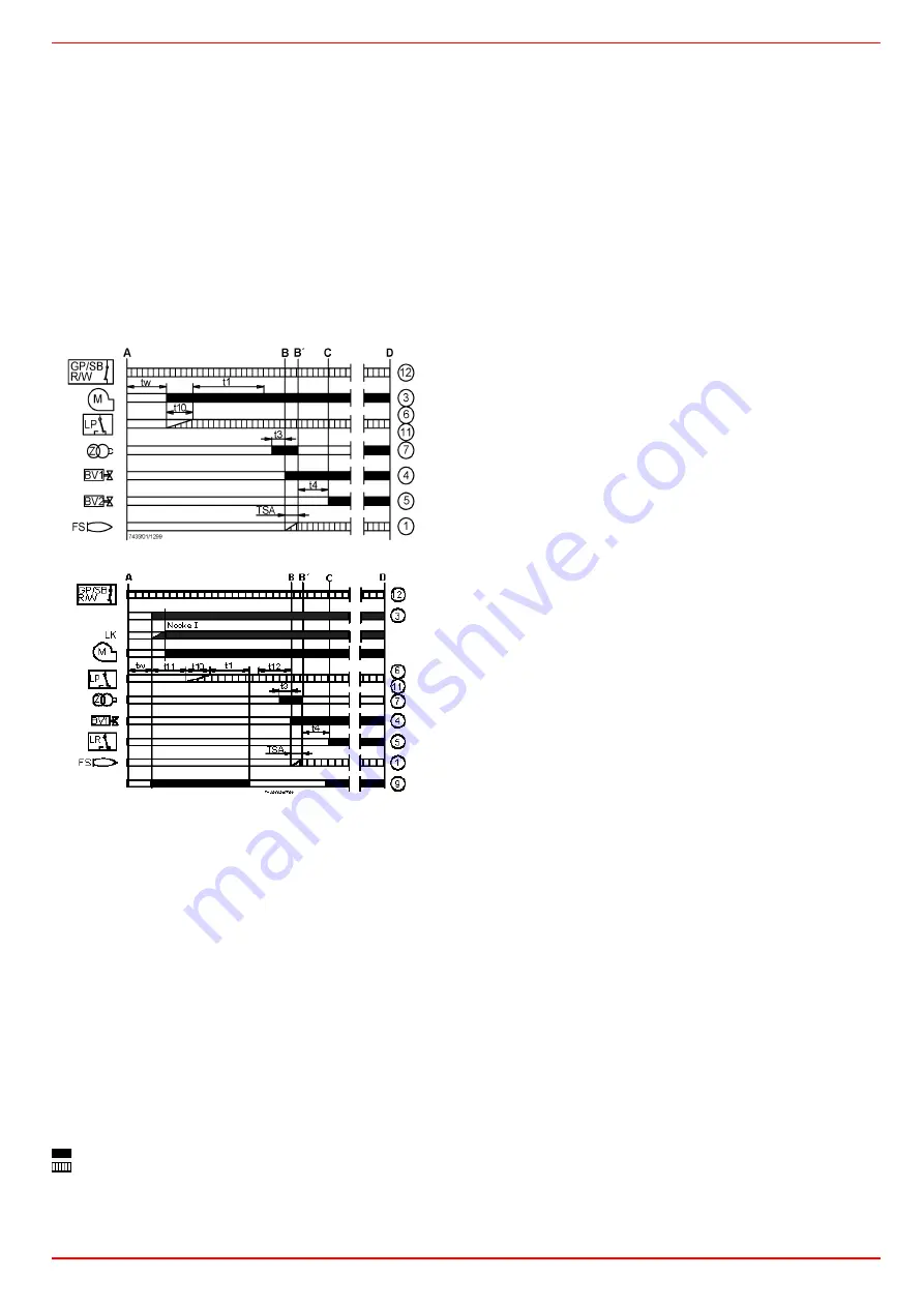
The programme run is shown in the diagrams. The required and permissi-
ble input signals for the control part and flame supervision part are pictu-
red as a hatching correspondingly in the function diagrams. If these input
signals are missing, the controller interrupts the start-up programme and
initiates a lock-out at the place where the safety regulations demand it.
The LGB types are fitted with under voltage protection, i.e. the load relay
AR is de-energized when the supply voltage falls below 160 V. The burner
control automatically attempts a new start-up when the supply voltage
again exceeds 160 V
A

Start-up command from the temperature or pressure
controller “R”

A-C

Start-up programme

C-D

Burner operation (heat production corresponding to the control
commands)

D

Controlled shut-down by “R”

LGB21

LGB22

Key for operation diagram

A - C Startup sequence
tw 

Waiting time, 8s for LGB21, 9s for LGB22

t1 

Prepurge time 30s

TSA  Ignition safety time 3s
t3 

Preignition time, 2s for LGB21, 3s for LGB22

t4 

Interval «BV1-BV2» or «BV1-LR», 8s

t10 

Specified time for air pressure signal, 5s for LGB21, 3s for LGB22 

t11 

Programmed opening time for actuator «SA», max. 12s

t12 

Programmed closing time for actuator «SA», max. 11s

BV

Fuel valves

FS

Flame presence signal

GP

Gas pressure switch

LP

Air pressure switch

LR

Load controller

M

Fan motor

R

Temperature or pressure controller

W

Safety thermostat or pressure switch

Z

Ignition transformer

1...12 Terminals of the burner flame controls on AGK11's socket

Command signal from flame control
Input signals

Conditions for starting up the burner:

z

The burner control must not be locked out.

z

The contacts of the gas pressure switch ”GP", the temperature or
pressure switch “W" and the controller “R", must be closed.

Start-up programme

A

Start command (switching on)

This command is triggered by control thermostat / pressure controller
«R». Terminal 12 receives voltage and the programming mechanism
starts running. On completion of waiting time «tw» with the LGB21..., or
after air damper «SA» has reached the nominal load position (on comple-
tion of «t11») with the LGB22..., fan motor «M» will be started.

tw

Waiting time

During the waiting time, air pressure monitor «LP» and flame relay «FR»
are tested for correct contact positions.

t11

Programmed opening time for actuator «SA»

(Only with LGB22...) The air damper opens until the nominal load position
is reached. Only then will fan motor «M» be switched on.

t10

Specified time for air pressure signal

On completion of this period of time, the set air pressure must have built
up, or else lockout will occur.

t1

Prepurge time

Purging the combustion chamber and the secondary heating surfaces:
required with low-fire air volumes when using the LGB21... and with nomi-
nal load air volumes when using the LGB22.... The diagrams show the so-
called prepurge time «t1» during which air pressure monitor «LP» must
indicate that the required air pressure is available. The effective prepurge
time «t1» comprises interval end «tw» through «t3».

t12 Programmed closing time for actuator «SA»

(Only with LGB22...)During «t12», the air damper travels to the low-fire
position.

t3 Preignition time

During «t3» and up to the end of «TSA», flame relay «FR» is forced to
close. On completion of «t3», the release of fuel is triggered at terminal 4.

TSA Ignition safety time

On completion of «TSA», a flame signal must be present at terminal 1.
That flame signal must be continuously available until shutdown occurs,
or else flame relay «FR» will be deenergized, resulting in lockout.

t4 Interval

LGB21...: time to the release of the second fuel valve «BV2»
LGB22...: on completion of «t4», the heat source is controlled depending
on the load (release of load controller «LR»)

B - B'

 Interval for flame establishment

C


Burner operation position

C - D

  Burner operation (heat production)

Operation of the burner at the maximum strenght or, with a flame control-
ler for the load.

D


Controlled by "R" shutdown

The burner stops, waiting for the next ignition.

Summary of Contents for HP20

Page 1: ...MANUAL OF INSTALLATION USE MAINTENANCE HP20 HP30 M039203CC REL 2 1 11 2012 BURNERS BRUCIATORI BRULERS BRENNER QUEMADORES ГОРЕЛКИ Progressive Fully modulating Gas light oil dual fuel burners ...

Page 2: ...e curves depending on the flow rate 17 Measuring the gas pressure in the combustion head 17 Pressure in combustion head gas rate curves 17 Gas Filter 18 VPS504 Gas proving system 18 Adjustments brief description 18 Adjustment procedure for gas operation 18 Calibration of air and gas pressure switches 20 Calibration of air pressure switch 20 Calibration of low gas pressure switch 20 Adjusting the h...

Page 3: ...ains electricity gas oil or other fuel z Observe caution with hot burner components These are usually near to the flame and the fuel pre heating system they become hot during the unit operation and will remain hot for some time after the burner has stopped When the decision is made to discontinue the use of the burner the user shall have qualified personnel carry out the following operations a Rem...

Page 4: ...of toxic or explosive mixtures DIRECTIVES AND STANDARDS Gas burners European directives Directive 90 396 CEE Gas Appliances Directive 2006 95 EC on low voltage Directive 2004 108 CEE on electromagnetic compatibility Harmonised standards UNI EN 676 Gas Burners CEI EN 60335 1 Household and similar electrical appliances Safety Part 1 General requirements EN 50165 Electrical equipment of non electric ...

Page 5: ...ps are provided with a pressure regulator except for some models for which a separate regulating valve is provided Other pumps are provided with two pressure regulators one for the high and one for low pressure in double stage systems with one nozzle The adjustable combustion head can improve the burner performance The combustion head determines the energetic quality and the geometry of the flame ...

Page 6: ...the necessary input and the pressure in combustion chamber are included in the burner performance curve otherwise the choice of the burner must be revised consulting the burner manu facturer To choose the blast tube lenght follow the instructions of the boiler manufacturer In absence of these consider the following z Cast iron boilers three pass flue boilers with the first pass in the rear part th...

Page 7: ... 2 gas valves gas proving system max pressure switch 8 GAS CONNECTION 25 Rp1 32 Rp11 4 BURNER TYPE HP20 HP30 Output min max kW 85 230 65 350 Fuel Natural gas Light oil Gas category see next paragraph Gas rate min max min max Stm3 h 9 24 3 7 37 Gas pressure min max mbar see Note 2 Light oil rate min max kg h 7 2 19 4 5 5 29 5 Oil viscosity 2 7 4 cSt 40 C Oil density 840 kg m3 Power supply 230V 1N 5...

Page 8: ...rred to burner fitted with extended blast tube GAS CATEGORY COUNTRY I2H AT ES GR SE FI IE HU IS NO CZ DK GB IT PT CY EE LV SI MT SK BG LT RO TR CH I2E LU PL I2E R B BE I2L NL I2ELL DE I2Er FR A B S B L C S C L D E F G H J K L M N P HP20 555 173 258 728 813 510 320 830 126 151 178 290 360 M10 370 155 HP30 555 300 855 510 320 830 150 162 178 290 360 M10 490 155 ...

Page 9: ...er to find a compromise between the burner output and the generator specifications that is why the minimum output may be different from the Per formance curve minimum Pressure in the network gas rate curves BACK PRESSURE IN COMBUSTION CHAMBER mbar HP20 kW HP30 kW GAS PRESSURE IN THE NETWORK mbar HP20 MG 25 Gas rate Stm3 h HP30 MG 25 32 Gas rate Stm3 h Caution the gas rate value is quoted on the x ...

Page 10: ...andle it according to the procedure described on paragraph Handling the burner 3 place the 4 stud bolts 5 on the hole of the boiler s door according to the burner s drilling plate described on paragraph Overall dimensions 4 fasten the 4 stud bolts 5 place the gasket on the burner flange 6 install the burner into the boiler 7 fix the burner to the stud bolts by means of the fixing nuts according to...

Page 11: ...utterfly gas valve ATTENTION BEFORE EXECUTING THE CONNECTIONS TO THE GAS PIPE NETWORK BE SURE THAT THE MANUAL CUTOFF VALVES ARE CLOSED READ CAREFULLY THE WARNINGS CHAPTER AT THE BEGINNING OF THIS MANUAL Gas train with valves group MB DLE with built in gas pressure governor VPS504 gas proving system 1 Burner 2 Butterfly valve 3 Gas proving system option 4 Maximum gas pressure switch optional 5 Mini...

Page 12: ...itions Fig 8 4 after installation perform leakage and functional test 5 disassembly in reverse order Once the train is installed connect electrically all its elements gas valves group pressure switches gas proving system ATTENTION once the gas train is mounted according to the diagram on Fig 4 the gas proving test mus be performed according to the procedure set by the laws in force ATTENTION it is...

Page 13: ... plants where gravity or ring feed systems are provided install an automatic interception device see n 4 Fig 12 Fig 9 Gravity circuit Fig 10 Ring circuit Fig 11 Suction circuit Key 1 Manual valve 2 Light oil filter 3 Light oil feeding pump 4 One way valve 5 Flexible hoses 6 Relief valve ...

Page 14: ...z Do not use fuel with additives to avoid the possible formation over time of compounds which may deposit between the gear teeth thus obstructing them z After filling the tank wait before starting the burner This will give any suspended impurities time to deposit on the bottom of the tank thus avoiding the possibility that they might be sucked into the pump z On initial commissioning a dry operati...

Page 15: ...el cover Pump Suntec AL65 Viscosity range 2 12 cSt mm2 s Oil temperature 0 60 C Inlet pressure 2 bar Minimum inlet pressure 0 45 barto avoid gasing Maximum return pressure 2 bar Rated speed 3600 rpm Respect the basic safety rules make sure of the connection to the earthing system do not reverse the phase and neutral connections fit a differential thermal magnet switch adequate for connection to th...

Page 16: ...C 16 Fig 13 Progressive burners Fig 14Fully modulating burners Fig 15 Probes connection Probes connection by means of the 7 pins plug Fig 16 see Fig 15 and the Electric wiring diagrams for connections Fig 16 Probe connector ...

Page 17: ...al pressure gauge Measuring the gas pressure in the combustion head In order to measure the pressure in the combustion head insert the pressure gauge probes one into the combustion chamber s pres sure outlet Fig 17 2 to get the pressure in the combustion chamber and the other one into the butterfly valve s pressure outlet of the burner Fig 17 3 On the basis of the measured differential pressure it...

Page 18: ...start flow rate anticlockwise rotation increases it Do not use a screwdriver on the screw VR Note the screw VSB must be removed only in case of replacement of the coil Attention z Beger actuator cams can be moved manually z Siemens actuator set the MAN AUTO lever to MAN to move the cams rememeber to set it to AUTO once the adjustment is accomplished ATTENTION before starting the burner up be sure ...

Page 19: ...e air dose the air according to the gas flow rate change following the steps quoted below 8 acting on the pressure stabiliser of the valves group adjust the gas flow rate in the high flame stage as to meet the values requested by the boiler utilisation Dungs MBC SE valves group act on its pressure governor to increase or decrease the pres sure and consequently the gas rate 9 To adjust the air flow...

Page 20: ...ase o the operation turn slowly the adjusting ring nut VR in the clockwise direction to increase the adju sting pressure until the burner lockout then read the value on the pressure switch scale and set it to a value reduced by 15 z Repeat the ignition cycle of the burner and check it runs properly z Refit the transparent plastic cover on the pressure switch Calibration of low gas pressure switch ...

Page 21: ...he operating flow rate downstream the gas governor gas valves group and upstream the butterfly valve by means of the adjusting ring nut VR set the value read on step 2 increased by the 30 4 replace the plastic cover Fully modulating burners To adjust the fully modulating burners use the CMF switch on the burner control panel see next picture instead of the TAB thermo stat as described on the previ...

Page 22: ...3 15 3 17 2 24 5 24 8 14 1 5 0 10 8 11 0 11 3 11 6 13 0 14 3 15 6 17 0 18 6 24 3 26 2 13 4 5 5 9 7 10 0 10 2 11 1 12 1 13 4 14 8 16 4 18 1 29 7 12 4 6 0 9 2 9 5 9 9 10 0 10 8 12 4 14 1 15 7 17 5 18 9 29 3 33 1 14 8 6 5 10 5 10 8 11 1 11 4 12 1 13 8 15 3 16 5 18 4 20 0 22 4 36 2 36 7 15 5 7 0 8 7 9 4 10 0 11 4 13 2 14 9 17 2 19 6 23 1 25 1 33 2 33 7 15 2 7 5 11 3 11 8 10 3 13 0 14 3 15 3 17 2 19 2 ...

Page 23: ...d para graph Attention z Berger actuator cams can be moved manually z Siemens actuator set the MAN AUTO lever to MAN to move the cams rememeber to set it to AUTO once the adjustment is accomplished 6 the nozzle supply pressure is already factory set and must not be changed Only if necessary adjust the supply pressure as fol lows see related paragraph insert a pressure gauge into the port shown on ...

Page 24: ... gas low flame microswitch cam III a little lower than the maximum position 90 10 set the TAB thermostat to the minimum in order that the actuator moves progressively towards the low flame position as far as fully modulating burners see the related paragraph 11 move the low flame cam to the minimum to move the actuator towards the low flame until the two bearings find the adjusting screw that refe...

Page 25: ...er The part of fuel that is not burnt goes back to the tank through the return circuit The fuel amount to be burnt is adjusted by means of the burner actuator according to the adjustments set see prevoius paragraph Fig 23 Stand by Fig 24 Prepurge Fig 25 Low flame Fig 26 High flame Key 1 Light oil pump 2 Light oil solenoid valve 3 Nozzle 4 Actuator 5 Adjusting cam 6 pressure gauge 7 Pressure regula...

Page 26: ...UCHING THEM SO AS NOT TO GET BURNT OPERATION z Choose the typer of fuel by turning the A switch on the burner control panel CAUTION if the fuel chosen is light oil be sure the cutoff valves on the feed and return pipes are open z Check the control box is not locked signalling light O on if so reset it by means of the pushbutton C z Check the series of thermostats and pressure switches turn the bur...

Page 27: ...oil valves opening the transformer is de energised and lamp L turns off z The burner is now operating meanwhile the actuator goes to the high flame position after some seconds the two stage operation begins the burner is driven automatically to high flame or low flame according to the plant requirements Operation in high or low flame is signalled by LED N on the burner control panel Modulating bur...

Page 28: ...ble flame shape appears Whenever the burner is used intensely we recommend preventively replacing the nozzle at the start of each heating season z Clean and grease sliding and rotating parts Removing the filter in the MULTIBLOC DUNGS MB DLE 405 412 z Check the filter at least once a year z Change the filter if the pressure difference between pressure connection 1 and 3 Fig 28 Fig 29 is p 10 mbar z...

Page 29: ...exible hoses 4 Loosen the screws V holding the gas manifold G loosen the two connectors E and remove the assembly as shown Note to replace the combustion head reverse the operations described above 5 Clean the combustion head by means of a vacuum cleaner scrape off the scale by means of a metallic brush Fig 28 Fig 29 Fig 30 1 0 5 34 5 3 4 6 6 2 1 3 pe 0 4 pa 5 pBr 0 3 pe 4 pa 6 1 5 pBr 2 H V E CE ...

Page 30: ...ustion head following the reversed pro cedure Cleaning and replacing the detection photocell The photocell working life is about 10000 working hours about 1 year at max 50 C after which it must be replaced To clean replace the detection photocell proceed as follows 1 Disconnect the system from the electrical power supply 2 Shut off the fuel supply 3 remove the photocell from its slot see next figu...

Page 31: ... 1 turn the burner s main switch to 0 Off position 2 disconnect the power mains 3 close the fuel valve in the supply line Burner disposal In case of disposal follow the instructions according to the laws in force in your country about the Disposal of materials Keys C Electrolytic capacitor 100 470 µF DC 10 25 V M Microammeter Ri max 5000 ohm QRA UV detector rt Red sw Black br Brown gr Grey bl Blue...

Page 32: ...ITHOUT GIVE CONSENT MAIN SWITCH OPEN z ABSENCE OF GAS z MINIMUM GAS PRESSURE SWITCH FAULT OR BAD SETTING z z z z BOILER THERMOSTATS OPEN z OVERLOAD TRIPPED INTERVENTION z FUSES INTERVENTION z AIR PRESSURE SWITCH FAULT OR BAD SETTING z z z z DEFECTIVE CONTROL BOX z z z z DEFECTIVE AIR DAMPER ACTUATOR z DEFECTIVE IGNITION TRANSFORMER z IGNITION ELECTRODE WRONG POSITION z THROTTLE VALVE BAD SETTING z...

Page 33: ...190341 GAS VALVE GROUP Rp1 1 4 Dungs MB DLE412 2190342 2190342 GAS PROVING SYSTEM 2190420 2190420 GAS PROVING SYSTEM 2191604 2191604 FLEXIBLE HOSE 2340002 2340001 SMALL ADJUSTING CAM FOIL 2440013 2440013 BIG ADJUSTING CAM FOIL 2440014 2440014 ACTUATOR BERGER STA12 2480053 2480053 ACTUATOR SIEMENS SQN72 24800A4 24800A4 UV PROBE 2510001 2510001 UV PROBE ADAPTOR Siemens AGQ1 1A27 2510101 2510101 UV P...

Page 34: ...USTION HEAD 52 BUSH 15 RING NUT 53 LEVERAGE 16 NET 54 ADJUSTING CAM 17 MOTOR 55 ACTUATOR 18 PLATE 56 ACTUATOR SHAFT 19 COUPLING 57 BRACKET 20 PUMP 58 AIR INTAKE DAMPER 21 BRACKET 59 AIR INTAKE DAMPER 22 FAN WHEEL 60 AIR INTAKE 23 MOTOR 61 LOUVER SHAFT 24 PRESSURE GAUGE 62 LOUVER SHAFT 25 PRESSURE GOVERNOR 63 THROTTLE SHAFT 26 BRACKET 64 ADJUSTING CAM SHAFT 27 GAS VALVES GROUP WITH GOVERNOR 65 ADJU...

Page 35: ...C I B UNIGAS M039203CC 35 ...

Page 36: ...M039203CC 36 WIRING DIAGRAMS ATTENTION 1 Electrical supply 230V 50Hz 1N a c 2 Don t reverse phase with neutral 3 Ensure to the burner a proper hearthing Progressive burners SE04 639 Fully modulating burners SE04 626 ...

Page 37: ......

Page 38: ......

Page 39: ......

Page 40: ......

Page 41: ......

Page 42: ......

Page 43: ......

Page 44: ......

Page 45: ......

Page 46: ......

Page 47: ......

Page 48: ......

Page 49: ......

Page 50: ......

Page 51: ......

Page 52: ... with the LME22 fan motor M will be started tw Waiting time During the waiting time air pressure monitor LP and flame relay FR are tested for correct contact positions t11 Programmed opening time for actuator SA Only with LME22 The air damper opens until the nominal load position is reached Only then will fan motor M be switched on t10 Specified time for air pressure signal On completion of this p...

Page 53: ...ed time for air pressure signal t11 Programmed opening time for actuator SA t12 Programmed closing time for actuator SA SB R W GP AL M LP BV1 Z FS tw t1 t3n TSA t4 7 t10 EK2 12 10 3 7 4 6 1 8 t3 A B B C D 11 SB R W GP AL LP BV1 LR BV2 Z FS tw t1 t3n t4 7101d05 0206 12 10 3 7 4 5 6 1 A B B C D t3 t10 M 11 SB R W GP AL LP SA BV1 LR BV2 Z FS tw t1 t3n TSA t4 7101d02 0606 t11 t12 EK2 12 10 3 7 4 5 6 1...

Page 54: ...t W Limit thermostat pressure switch Z Ignition transformer LME22 connection diagram NT PC control RESET EK FSV ION 1 2 3 M 4 BV1 5 7 Z 10 AL T 12 R W GP STB 9 7101 24 0606 pa 6 LP 8 EK 11 K1 K2 1 K3 K2 2 H Si L N NT RESET EK FSV ION 1 2 3 M 4 BV1 5 BV2 7 Z 10 AL T 12 R W GP STB 9 pa 6 LP 8 EK 11 K1 K2 1 K3 K4 K2 2 H Si L N PC control NT PC control RESET EK FSV ION 1 2 3 M 4 BV1 5 BV2 7 Z 10 AL T ...

Page 55: ...or code table the device repeats the blinks for regular intervals During diagnostics the control outputs are deactivated the burner remains shut down external fault indication is deactivated fault status is showed by the red LED inside the LME s lockout reset buttonaccording to the Error code table RESETTING THE BURNER CONTROL When lockout occurs the burner control can immediately be reset by pres...

Page 56: ... pressure controller R Terminal 12 receives voltage and the programming mechanism starts running On completion of waiting time tw with the LGB21 or after air damper SA has reached the nominal load position on comple tion of t11 with the LGB22 fan motor M will be started tw Waiting time During the waiting time air pressure monitor LP and flame relay FR are tested for correct contact positions t11 P...

Page 57: ... safety appliance is located a plexiglass lunette under which there is the indicator disc of programme s progress In the event of safety stop the programmer stops The disc shows as fol lows the position of the programme at which the interruption occurred no start up the command ring is open interval tw or t10 on LGB21 tw or t11 on LGB22 air damper open LGB22 safety stop block through absence of th...

Page 58: ...or pressostat W Safety thermostat or pressostat Z Ignition transformer Key programmer s diagram A start up command from regulator R B burner operation C program start position start up tw waiting time t1 preventilation time TSA safety time t3 pre ignition time t4 interval of time BV1 BV2 or BV1 LR t10 waiting time for confirmation of air pressure t11 air damper movement time to open position t12 a...

Page 59: ......

Page 60: ... and data subject to change Errors and omissions exceptd C I B UNIGAS S p A Via L Galvani 9 35011 Campodarsego PD ITALY Tel 39 049 9200944 Fax 39 049 9200945 9201269 web site www cibunigas it e mail cibunigas cibunigas it ...

Reviews: