background image

27

2. 

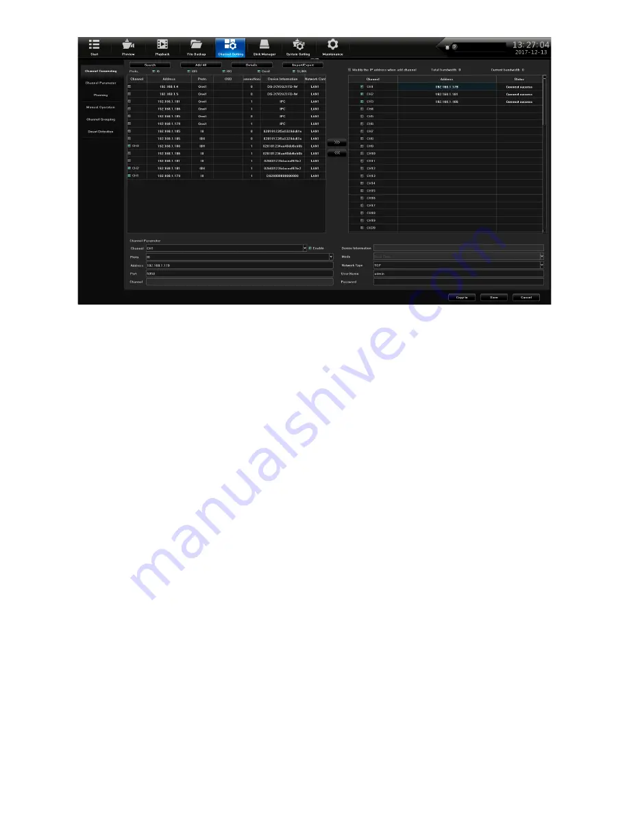
In the left column, put a check next to the cameras that you want to assign to a channel. Don't 

worry about the order of channels at this time. As they are checked, the IPC should show up on 

the right side with a channel number. Follow these guidlines:

•   2MP, 4MP, and 4K cameras - select the IPC with the SLINK protocol (Proto. column).

•   IPCs included in a XVR kit - select the I8S protocol for these IPCs.

• 

 IPCs that only show I8 - use this protocol if none of the above don't apply.

•   If you are not using a Uniden IPC, select the Onvif protocol.

•   If the IPC does not show up, check the IP address and the network, and try again.

3.  When the IPC shows up on the right side, it will automatically be assigned the next channel 

number. After a few seconds, the Status column should display 

Connect success

 for each 

channel. f not, make sure the IPC and the LAN are in the same IP range.

4.  On the left side, double left-click the IP address to display the 

IPS Details 

pop-up. Review IP 

address and Subnet Mask. If you are using a non-Uniden IPC, you must create a user name 

and password. Click 

Modify

, make changes/enter a user name/password, click 

Modify, OK

and finally 

Exit

. Close the window and return to the 

Channel Connecting

 screen.

5.  From 

Channel Setting/Channel Parameter/Display Setting

, select a channel in the 

Channel


drop down list. Check the 

Show Local Channel Name

 box to create a name to display for that 

channel (un-check this box if you do not want the name to show up in the picture).

6.  After all cameras are connected and working, go to the 

Preview

 screen and show all cameras. 

You can put the cameras in whatever display order you want. With the mouse, click and drag 

a camera from its current layout location and drop it in another location to swap locations. 

Confirm the swap in the pop-up confirmation screen.

ANALOG CAMERA SETUP

The ProSeries cameras connect to the XVR systems via a BNC connector, which is analog video 

or Hi-Definition over coax.  These cameras have setting menus that can be changed using the 

UTC (Up The Coax) menu on the XVR. 
1. 

Power up the XVR and login to the system. Go through the Guide screens and configure the 

system. 

2.  Connect the camera to the XVR using the BNC connectors.

Summary of Contents for PRO400X1

Page 1: ...ProSeries XVR TECHNICAL INSTALLATION GUIDE PRO400X1 PRO800X2 PRO1600X2 2018 Uniden America Corporation Irving Texas Issue 1 June 2018 For trained service installation personnel only...

Page 2: ...consumer s use of these products to be in compliance with all local state and federal law For further information on video surveillance and audio recording legal requirements please consult your local...

Page 3: ...ION 11 INSTALLATION REQUIREMENTS 11 HARD DISK INSTALLATION 11 HARD DISK INSTALLATION 11 CLEAR DISK MISSING ALARM 12 DISABLE DISK MISSING ALARM 12 NETWORK CONNECTION SCHEMATIC DIAGRAM 14 INITIAL TURN U...

Page 4: ...ves 26 Formatting the HDDs Optional 26 CAMERA SETUP 26 IP CAMERA SETUP 27 Set up IP Addresses 28 Adding Optional IP Cameras 28 ANALOG CAMERA SETUP 29 SET UP CHANNEL GROUPS 30 Name Channels 30 Create a...

Page 5: ...a basic installation checklist with accompanying procedures for each step The Installation Guide text confirms to the following nomenclature Italic text indicates a screen name menu selection etc It...

Page 6: ...lly or remotely through a web browser DEFAULTS Administrator user name admin Administrator password No password leave blank LAN1 IPv4 address DHCP auto enabled Default video resolution 1280 x 1024p Fa...

Page 7: ...4 HDMI Video Out 9 Power Input 5 VGA Video Out 10 Power Switch Cameras connect to LAN1 PoE gigabit network switch PRO800X2 1 10 9 8 7 6 5 4 3 2 1 BNC Camera 6 RJ45 Network Port 2 Audio In 7 USB 2 0 3...

Page 8: ...9 1 8 7 6 10 1 Jacks Audio In 6 Accessories Out 2 BNC Cameras 7 Power Input 3 Audio Out 8 Power Switch 4 HDMI Video Out 9 USB 2 0 5 RJ45 Network Port 10 VGA Video Out Cameras connect to LAN1 PoE giga...

Page 9: ...stern Digital Purple or Seagate SkyHawk surveillance hard drives when adding a hard disk drive Verify that the XVR power supply and AC outlet are reliably grounded HARD DISK INSTALLATION The following...

Page 10: ...ding again The only way to fully clear the alarm is to correct the condition that caused the alarm in the first place 1 From Disk Manager Storage Management uncheck any Missing Alarm column boxes 2 Cl...

Page 11: ...ion populated along its row If a row is not populated with a HDD uncheck the box in the Missing alarm column to disable this alarm for this uninstalled HDD 4 Repeat this procedure for every installed...

Page 12: ...AM PRO400X1 PRO800X2 or PRO1600X2 1 BNC cable per camera connects to XVR Bullet Camera Dome Camera XVR NETWORK CONNECTION SCHEMATIC Although it is not required at this point in the installation you ma...

Page 13: ...limited power source must be used for alarm inputs _______ From System Setting Network Parameter Email Setting top tab set up email notification see page 21 _______ From System Setting Network Paramet...

Page 14: ...ble _______ Set individual camera settings for each channel if desired see page 33 Other areas to set up include but are not limited to Motion Detection From Channel Setting Channel Parameter Motion t...

Page 15: ...these screens to configure the system Language setting Select user language Default ENGLISH as shown in figure 5 3 Click Next Display setting Select the screen resolution Default 1280x1024 P60 Click N...

Page 16: ...s The correct procedure for disposing of different types of batteries may vary significantly by region Check the website for your state city or municipality for information on how to dispose of batter...

Page 17: ...t side tab A list of users displays 2 Click Add User on the bottom right side of the screen The Add User screen displays 3 Enter the information for a new user a popup keyboard displays and select the...

Page 18: ...s for recording in military time 24 hour format 00 00 23 59 Copy the scheduled recording time to all days or to specific days Select OK The Recording Setting screen displays again with the new recordi...

Page 19: ...gger motion detection select Clear all then click and drag the curser over the area you want to trigger recording This creates a specific red grid Everything outside of the red grid will NOT trigger m...

Page 20: ...lete the fields Click Save if your are finished Click Copy To to copy the setting to other channels The Copy To screen displays 3 Uncheck the options you don t want to copy Click All copy to all chann...

Page 21: ...er channels and then click Save when finished SET UP EMAIL NOTIFICATION 1 Go to System Setting Network Setting Email Setting top tab The Email setting screen displays 2 Fill in fields using the pop up...

Page 22: ...er the other fields as needed Server Type Server Domain Name Port User Name Password Confirm Password Device Domain Name Update Intercal in minutes 3 Click Save then Confirm when complete CHECK FIRMWA...

Page 23: ...or more than one if supported by the recorder and then format it to create a standard sequential read write configuration When the first disk gets full then the second HDD will be written to and then...

Page 24: ...nd formatting progress The system will give an audible alarm during this process Click Confirm to close the Format Complete pop up window 5 To be safe uncheck the Format box in the HDD row click Save...

Page 25: ...f the camera is 4MP or higher but halves the maximum number of cameras 5 After the selection is made select Save in the bottom right corner 6 A pop up window will warn that the system will need to be...

Page 26: ...ddress open a web browser on a remote computer or device and access the IP cameras or the recorder 7 If a WiFi access point is connected to the LAN connect the Uniden ProSeries Mobile app or via a web...

Page 27: ...e using a non Uniden IPC you must create a user name and password Click Modify make changes enter a user name password click Modify OK and finally Exit Close the window and return to the Channel Conne...

Page 28: ...SD On Screen Display of the camera s Main menu see picture below 7 Adjust the camera s settings SET UP CHANNEL GROUPS You can name your channels and then put them into collections called groups For ex...

Page 29: ...w groups tab select a Preview group on the right side to add cameras to 2 On the left side select the channels to add Click to add the channels to the selected Preview group These channels now display...

Page 30: ...isplays again Click Confirm 4 The new tour group displays 5 Select the tour group to add cameras to See A in the following graphic Select the cameras that belong in that tour group see B in the follow...

Page 31: ...s graphic The selected camera moves either up or down in display order SET UP PTZ CAMERA S Configure PTZ Camera From System Setting PTZ Setting set the following parameters Channel Protocol Decoder Ad...

Page 32: ...splays 3 Repeat these steps for all the areas you want to view with this camera Set Up PTZ Cruise PTZ cruises use presets to create a cycle of camera images from preset positions Set up Presets first...

Page 33: ...Change positions 4 Repeat the previous step until you are finished recording Go back to the Pattern tab and click Stop recording 5 Double click on the Pattern Path Name and rename it through the popu...

Page 34: ...Time Date Time Format Date Format Image Setting Camera lens parameters The parameters vary according to the type of camera you are configuring A PTZ camera may have different parameters than an IP cam...

Page 35: ...Detection Planning Linkage Operation Full screen Clear all To select specific areas to be triggered click Clear all to clear the grid from the screen Then click and drag over areas you want to be affe...

Page 36: ...ty keypad from being viewed When you have the screen set up how you want it click Save the area selected becomes a black box Click Exit on the confirmation screen Parameters are Channel Enable Privacy...

Page 37: ...elect Channel Setting Channel Parameter Video Tampering tab you can set that channel to record in a read only propriatery I8 video format Parameters are Channel Enable Video Tampering Sensitivity Plan...

Page 38: ...38 Smart Detection When you select Channel Setting Smart Detection logarithms activate based on the tab settings These tabs are Target Counting Left lost Area Detection Line Crossing...

Reviews: