background image

Operation

HT-Series | Version 1.01

15

Unevenly distributed longitudinal direction:

The load is distributed over half of the platform (longitu-
dinal direction). 33% of the nominal load is permitted.  

Fig. 9: Unevenly distributed longitudinal direction

9.5 Lifting and lowering the load

Lifting

Before the lift table platform is raised, the lift table must 
first be fixed in place by the rollers. 

By repeatedly pressing the lever (Fig. 10), the platform 
moves upwards. Lock the brakes before lifting and lo-
wering loads.

Fig. 10: Lifting the lift table: HT 300 (top), HT 300 L (bottom)

Fig. 10: Lifting the lift table: HT 600

Make sure that you do not place any body parts (hands, 
legs, etc.) under the table when the load is lifted. There 
is a high risk of injury! 

Lowering

The same requirements that applied in the previous 
chapter apply here. 

By lifting the lever (Fig. 11) the platform moves down-
wards (HT 300 S, M, M PSR, HT 600). 

Fig. 11: Lowering the lift table: HT 300 S, M, M PSR (top), 

HT 600 (bottom)

Summary of Contents for HT 300 S

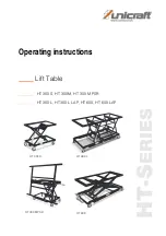
Page 1: ...HT S ERIES HT 300 S Operating instructions Lift Table HT 300 S HT 300 M HT 300 M PSR HT 300 L HT 300 L LAP HT 600 HT 600 LAP HT 300 M PSR HT 600 HT 300 L ...

Page 2: ...Symbol explanation 3 2 2 Obligations of the operating company 4 2 3 Requirements to staff 5 2 4 Personal protective equipment 5 2 5 Safety instructions 5 2 6 General safety regulations 6 2 7 Safety regulations 7 2 8 Safety instructions for operating personnel 7 2 9 Safety labels on the lift table 8 3 Intended Use 8 3 1 Residual risks 8 4 Technical Data 9 4 1 Table 9 4 2 Type plate 9 5 Transport pa...

Page 3: ... always interested in valuable experience and knowledge gained from using the application which then could be shared and be valuable to develop our products even further 1 3 Limitation of liability All information and notes in these operating instructions were summarised while taking applicable standards and rules the state of the art technology and our long term knowledge and experiences into con...

Page 4: ...essary The operating company must unambiguously reg ulate and determine the responsibilities for instal lation operation troubleshooting maintenance and cleaning The operating company must ensure that all per sons who work with the lift table have read and understood this manual Furthermore she must in struct the staff in regular intervals and inform them about the hazards The operator must provid...

Page 5: ...tec tive equipment while performing different tasks on and with the machine which are indicated in the individual paragraphs of these instructions The personal protective equipment is explained in the following paragraph 2 5 Safety instructions The lift table may only be operated at sufficiently il luminated workstations The lift table is intended for lifting lowering and moving loads The lift tab...

Page 6: ... minimum age 18 years who are familiar with these operating instructi ons in particular the safety regulations should be au thorised to do the work All other regulations on work safety and accident pre vention must be observed The operator must issue operating instructions Obligations of the staff The following general safety regulations must be obser ved The operator is responsible for the safe u...

Page 7: ...t be ensured that the user can operate the lift table with the load without any problems We point out that in case of improper use no liabi lity for possible consequential damages can be assumed This also applies to the use of the lift ta ble that are not suitable for use as well as any un authorized alteration to di esen in particular for the replacement of original parts with parts of other orig...

Page 8: ... on firm level ground in perfect condition and only by instructed persons Intended use also includes compliance with all information in these instructions Any use beyond the intended use or any other use is considered misuse Misuse Lifting moving and transporting of persons Operation in potentially explosive areas Stürmer Maschinen GmbH accepts no liability for de sign and technical changes to the...

Page 9: ...0 300 300 300 600 600 Table height min mm 400 400 400 400 430 400 430 Table height max mm 1010 1010 1010 1010 1040 1010 1040 Roll diameter mm 125 125 125 125 125 125 125 Max plate weight for swivel frame kg 120 Length swivel frame mm 1800 Width swivel frame mm 1500 Type HT 300 S HT 300 M HT 300 M PSR HT 300 L HT 300 L LAP HT 600 HT 600 LAP Required space BxWxT mm 1000 x 400 x 610 with work table 1...

Page 10: ...are recyclable and should be taken to a materials recycling depot to be disposed of The delivery packaging is made of cardboard so please dispose carefully by having it chopped up and given to the recycling collection The film is made of polyethylene PE and the cushioned parts of polystyrene PS These materials should be taken to a collection point for recyclable materials or to the local waste dis...

Page 11: ...ump to the hydraulic cylinder Foot pump and hydraulic cylin der are a fixed unit HT 300 M PSR Provides one person with easy loading of panels onto the platform frame and pivoting from vertical to horizontal position Swivel frame with two layer locking in vertical and horizontal position 6 2 Accessories work plates optional HT 300 S Smooth metal work plate 1000 x 600 mm Beech multiplex work plate 1...

Page 12: ...ionof the lift table into the existing ma chinery must be carried out in such a way that the basic safety requirements of the EC Machinery Di rective 2006 42 EC are observed must be chec ked by the operator of the lift table the environment must not be potentially explosive These operating instructions and any other asso ciated operating instructions must be read and un derstood 8 1 HT 300 M PSR D...

Page 13: ...lift table the operator must ensure that there is no danger from the movement of the lift platform DANGER DANGER TO LIFE DUE TO FALLING OF THE LOAD Falling loads can cause serious injury or death Never exceed the specified maximum load Never move the lifted load Never work under the lifted load Observe the load manufacturer s instructions on the load application point Distribute the weight central...

Page 14: ...against fal ling by suitable equipments However it is usually not necessary to secure the load It is only necessary for loads that have an unstable position on the lift platform e g rolling elements Load balancing The nominal load of the lift table is based on a load evenly distributed on the platform If this nominal load is not evenly distributed on the platform the nominal load must be reduced a...

Page 15: ...llers By repeatedly pressing the lever Fig 10 the platform moves upwards Lock the brakes before lifting and lo wering loads Fig 10 Lifting the lift table HT 300 top HT 300 L bottom Fig 10 Lifting the lift table HT 600 Make sure that you do not place any body parts hands legs etc under the table when the load is lifted There is a high risk of injury Lowering The same requirements that applied in th...

Page 16: ...nance or repair work has been carried out on the lift table a function test must then be carried out It is forbidden to reach into the lift if it is not secu red by the maintenance support Wear suitable protective clothing wear safety shoes Maintenance and repair work may only be carried out by competent trained and instructed personnel Energy supply systems must be interrupted If necessary furthe...

Page 17: ...Models HT 600 and HT 600 LAP Check the hy draulic oil level at regular intervals Step 4 Make sure that all safety notices on the lift table are clearly legible Check oil level only models HT 600 and HT 600 LAP Oil changes Step 1 Lower the lift table and open the cap on the pump tank filler neck For oil change Drain used oil Step 2 Top up oil HLP 32 if necessary or when changing oil Oil tank volume...

Page 18: ... condition of the compo nents and equipment the completeness and effective ness of the safety equipment and the completeness of the test book If a test period of no more than one year is adhered to the operator can assume that this period is adequate Verification of scissor lift tables must be veri fied by a log book 12 Disposal recycling of used devices Please take care in your own interest and i...

Page 19: ...ering spare parts send a copy of the spare parts drawing with the marked component guide roll and marked item number 13 to the authorised dealer or to the spare parts department and provide the following information Type of device Lift Table HT 300 S Artikelnummer 6100300 Position number 13 In case of service the following drawing shall help to identify the necessary spare parts Faults Possible ca...

Page 20: ...g lever 8 1 19 001 060 02 Foot bar 4 3 DIN 125 A17 Washer 8 2 19 001 060 03 Fastening 4 4 DIN 625 T1 6203 2RS Deep groove ball bearing 8 3 DIN 913 MS x 20 Threaded pin 4 5 ISO 10511 M16 Hex nut 8 4 ISO 4032 MS Hex nut 4 6 ISO 4014 M16 x 65 Hex bolt 8 5 ISO 4762 MS x 45 Allen screw 4 7 ISO 4017 M16 x 45 Hex bolt 9 ISO 4017 M12 x 30 Hex nut 5 19 001 030 00 AA Scissors large cpl 10 ISO 4017 MS x 10 H...

Page 21: ...O 4032 M8 Threaded pin 6 5 ISO 4014 M16 x110 Hex bolt 3 5 ISO 4762 M8 x 45 Allen screw 6 6 ISO 4014 M16 x 65 Hex bolt 4 19 020 011 00 AA Base frame 7 19 020 041 00 AA Support frame 5 19 020 020 00 AA Scissors small cpl 8 19 020 051 00 AA Pressure fork 5 1 19 020 021 00 AA Scissors small 9 ISO 4017 M8 x 10 Hex nut 5 2 19 020 061 00 Locking lever right 10 ISO 4017 M12 x 30 Hex nut 5 3 19 020 063 00 ...

Page 22: ...0 AA Support frame 8 19 020 051 00 AA Pressure fork 10 ISO 4017 M8 x 10 Hex nut 9 ISO 4017 M12 x 30 Hex nut 11 ISO 4762 M8 x12 Allen screw 12 DSCO101 12 82 Medipack 13 L IL PUZK 125 K 3 Guide roll 14 L IL PUZK 125 K 3 DSN Guide roll with brake Pos Item number Description 1 19 020 282 00 Support frame 1 1 19 020 282 02 Safety guard 1 2 19 020 282 03 Threaded plate 1 3 19 020 283 00 Support frame 1 ...

Page 23: ... Scissors large cpl 9 Wheel base cpl 4 1 Bolt 9 1 Rectangular tube 4 2 Scissors large 9 2 Hex bolt 4 3 Washer 9 3 Tube cover 90x40x4 4 4 Lock ring 9 4 Guide roll 4 5 Groove ball bearing 10 Base frame cpl 4 6 Hex nut 10 1 Axle under cylinder 4 7 Hex bolt 10 2 Base frame 4 8 Hex bolt 10 3 Locking ring 5 Support frame 11 Pressure fork cpl 6 Safety cap 11 1 Axle upper cylinder 6 1 Connecting plate 11 ...

Page 24: ...sors small 4 10 DIN 471 25 x1 2 Locking ring 3 5 DIN1850 G 22x32 x20 Bearing 4 11 DIN 471 28 x 1 5 1 Locking ring 3 6 DIN 1850 G 28x32 x30 Bearing 4 12 DIN 625 T1 6304 2RS Groove ball bearing 3 7 DIN 471 20 x1 2 1 Locking ring 4 13 DIN 988 28 x 40 x 2 Fitted washer 3 8 DIN 471 22 x1 2 1 Locking ring 4 14 Rohrdeckel 100x40x6 Tube cover 100x40x6 3 9 DIN 471 25 x 1 2 Locking ring 5 19 160 041 00 Supp...

Page 25: ... to the information on the type plate complies with the relevant fundamental safety and health requirements of the above mentioned EC Directive and the other directives applied hereinafter including their amendments valid at the time of the declaration due to its con ception and design as well as in the version placed on the market by us The following harmonized standarts were applied EN ISO 12100...

Page 26: ...www unicraft de ...

Reviews: