


17
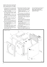
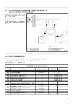
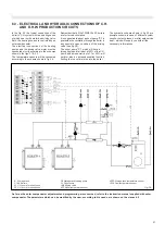
fig. 17
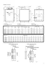
TRISECAL 3P 120÷350
1
Thermometer bulb
2
Working thermostat bulb
3
Minimum thermostat bulb
4
Safety thermostat bulb
5
Bulb retaining clip
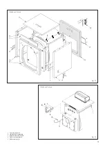
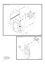
Assembly of the casing for TS 3P 450 to 600
should be carried out in the following steps:
Refer to diagram on fig. 18 & 19 for details:
A) Fit to the front and rear tube plates the
four upper brackets (pos. 1), supporting
the side panels, using the screws,
washers and nuts supplied (pos. 2, 3 and
4).
B) Fit to the front and rear tube plates the
four intermediate and lower brackets (pos.
5) supporting the side panels, using the
screws, washers and nuts supplied (pos.
2, 3 and 4).
C) Fit the insulation blanket (6) onto the boiler
shell and secure it in to place using the
elasticated straps (7) provided, ensuring
that the metal clips grip in to the external
surface of the insulation.
D) Position the side lower panels (pos. 9 and
18) onto the lower and intermediate
brackets (pos. 5).
To determine which one is the left or right
hand side panel ensure that the cable
clamp plate holes are positioned facing
toward the front edge.
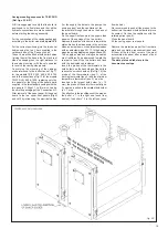
E) Position the side upper panels (pos. 8 and
17) onto the upper brackets (pos. 1) and
fix their pivots on the lower side.
F) Fit the 8 screws (pos. 10) to the upper
part of the front and rear counter bend of
the upper panels (pos. 8 and 17).
G) Fit the front insulation (pos. 11), inserting
the hinges in the insulation pre-cuts.
Note: because the front insulation is suitable
for two different boiler ranges (TX N and
TS 3P), before removing the precut
insulation, follow the instructions supplied
with the insulation it self.
H) Fit the rear insulations (pos. 16 and 27)
and fix the rear upper panel (pos. 26).
I) Position the panels 12 and 19 between
the side upper panels (pos. 8 and 17).
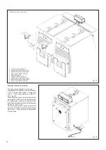
L) After removal of the two side screws from
the panel board rotate its cover towards
the front and insert the cables and the
capillaries of thermometer and thermostats
through the slots on its base.
Fit the panel board to front upper panel
(13).
Fit the upper panel (13), complete with
the panel board to the side upper panels
(8 & 17).
Guide the burner plug through the side
cable clamp plate (14) on the preferred
side and clamp the cable using the cable
clamp supplied.
Fix the side cable clamp plates (14) to the
casing side panels (9 & 18).
Fit the cables, leaving the boiler from the
back side, with the plastic screws of the
cable clamps (20).
M) Insert the thermometer and thermostat
bulbs in the bulb holders as shown in fig.
19 and connect the mains, the burner, the
pump(s) and any ancillary equipment to
the panel board.
Close the panel board.
N) Fit the cable clamps (pos. 20) onto the
rear panel (pos. 19) and clamp the cables.
O) Fit the longitudinal upper panels (pos. 21
and 25) to the side panels.
P) Remove the protective paper film from
data plate and ventilation requirement label
(14) and fit them at the top front corner of
the most accessible side panel after
removal of dust from the surface.
The data plate and label are in the
documents envelope.