background image

12

2.5.6 - CONNECTION OF THE

EXPANSION PIPE AND VESSEL

An expansion vessel is always necessary, to
compensate the water volume increase due
to the heating.
The TS 3P boilers are suitable for fully pumped
systems, which can be open vented or sealed.
In the 1

st 

case the height of the hydrostatic

column must be, at least, 3 m above the boiler
casing and the capacity of the expansion
cistern shall be able to contain, between the
water surface and the overflow pipe, the
volume increase of all the water of the C.H.
system. Preference shall be given to high and
narrow cisterns, to expose to the air a surface
as small as possible, thus reducing the water
evaporation.
In the 2

nd

 case the vessel capacity has to be

calculated taking into consideration:

-

The total volume of the water contained
in the system.
The maximum working pressure of the
system (see setting of PRV).

-

The maximum working pressure of the
expansion vessel.

-

The initial preloading of the expansion
vessel.

-

The maximum working temperature of the
boiler (the maximum setting of the
thermostat fitted onto the panel board is
90 °C; under this aspect it it suggested to
consider 100 °C.

The expansion pipe connects the C.H.
system to the expansion vessel.
This pipe which starts from the connecting
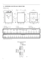
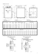
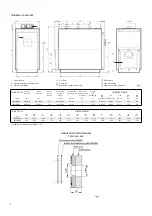
point T3 (see table DIMENSIONS), must have
NO gate valve on it.

2.5.7 - SHUNT PUMP

The TRISECAL 3P boilers must be operated
under forced water circulation and at a minimum
water temperature of 30 °C, if operated with
oil, or 35 °C, if operated with natural gas,
when the boiler is used in sliding temperature
and at part load (see par. 7.2).

In the C.H. systems equipped with mixing
valve it is convenient to foresee a shunt pump
Pr to guarantee the necessary water circulation
through in any possible opening condition of
the mixing valve and to guarantee therefore
the respect of the minimum return temperature
indicated.

This pump will be sized according to the
following formula:

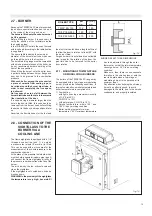
Q = P x 22

where Q = Water flow rate in liter/h

P = Boiler nominal output in kW

and the manometric head  1-2 m w.c.

2.6 - FURNACE DOOR:

ADJUSTMENT,
OPENING & CLOSING

A special attention has been paied to the
design of the front door, because in all the
pressurised boilers a good quality of the doors
is a necessary condition for the best operation
of the boiler.
With the furnace working in positive pressure,
in fact, every minimum fissure could cause a
leakage of high temperature combustion
products, with consequent burning of the
gasket and overheating of the door up to its

permanent deformation.
For these reasons the door structure of the
TS 3P boilers, in addition to the fact to be
very strong, has also the possibility to be
adjusted: it can be lifted, lowered and also
slanted, getting, thus, always the perfect
centering of the sealing gasket.
The special inner lining in ceramic fiber
reduces, furthermore, the time to reach the
boiler steady state condition and then reduces
drastically the formation of condensate at the
boiler start.

An interesting particularity related to the front
door, is the soundness self keeping system,
made with elastic steel plates which compen-
sate and reposition the door exactly onto the
sealing rope, also in case the ceramic fiber
sealing rope becomes hard.

2.6.1-  IMPORTANT NOTE

Before opening the furnace door it is necessary
to adopt the following precautions:
-

Close the fuel cock (oil or gas) to the burner.

-

Cool down the boiler by keeping the water
circulating through it, and only then switch
off the power.

-

Put on the boiler a Warning notice with
the following text: DO NOT USE, BOILER
UNDER SERVICE, OUT OF ORDER.

Summary of Contents for TRISECAL 3P Series

Page 1: ...aaaaa 07 04 TRISECAL 3P TRISECAL 3P DUO INSTALLATION USE AND SERVICING INSTRUCTION to be kept by the user...

Page 2: ...responsibility of the installer to fulfil all the regulations concerning the boiler house the safety devices the chimney the fuel supply lines the electrical installations and all the other local req...

Page 3: ...age 21 3 2 Functions descriptions page 21 OPTIONAL PANEL BOARD WITH OUTER COMPENSATOR page 22 4 1 Functions description page 22 4 2 Panel board with outer compensator on request page 23 4 3 Electrical...

Page 4: ...ystems BS 5546 Installation of gas hot water supplies for domestic purposes 2nd Family Gases BS 6644 Ventilation for gas appliances of rated input exceeding 60 kW HEALTH SAFETY DOCUMENT No 635 The Ele...

Page 5: ...e equipped with a reversible hinged door which can be opened for this reason from L H or R H side The outer shell is insulated with a glass wool 1 2 WORKING PRINCIPLE The NOx formation process is stro...

Page 6: ...0 T4 ISO 7 1 Rp Rp T3 ISO 7 1 Rp1 Rp1 T1 T2 ISO 7 1 Rp1 Rp1 Weight with packaging kg 326 398 Maximum boiler working pressure bar 5 5 Smoke side pressure drop mm w c 3 5 5 5 5 7 5 Water side pressure d...

Page 7: ...20 8 377 204 270 289 320 412 478 0 06 0 08 0 08 0 10 0 10 0 18 0 17 0 20 0 22 0 35 0 32 0 53 6 8 5 7 10 12 17 22 24 18 26 18 26 5 5 5 5 5 5 486 575 626 739 949 1118 DN 50 DN 50 DN 65 DN 65 DN 80 DN 80...

Page 8: ...O mm Hydraulic resistance for delta T 15K 210 210 TS 3P 450 TS 3P 600 TS 3P 450 TS 3P 600 2 1 TRISECAL 3P Type T6 i mm T5 i mm T4 ISO 7 1 T3 UNI 2278 PN16 T1 T2 UNI 2278 PN16 Weight with packaging kg...

Page 9: ...rent models W mm B mm 1080 1210 1275 1470 1605 1800 A mm 1730 1730 1790 1790 1850 1850 Pressione max esercizio caldaia bar 5 5 5 5 5 5 Smoke side pressure drop mm w c 12 17 22 24 18 26 18 26 20 28 20...

Page 10: ...nd it should also comply with any relevant requirements of the local gas supplier local authority and the relevant Standard Codes of Practice and building regulations The boiler house must be ventilat...

Page 11: ...of the boiler Among the inconvenients caused by the bad quality of the feeding water the most frequent and serious is the scaling of the heat exchange surfaces Less frequent but also dangerous is the...

Page 12: ...the necessary water circulation through in any possible opening condition of the mixing valve and to guarantee therefore the respect of the minimum return temperature indicated This pump will be sized...

Page 13: ...h a pressure test nipple 9 mm dia is fitted This can be used with a silicon pipe for the measurement of the counterpressure in the combustion chamber At the place of this pressure test nipple which mu...

Page 14: ...ith the panel board to the side panels 3 4 G Insert the thermometer and thermostat bulbs in the bulb holders as shown in fig 15 and connect the mains the burner the pump s and any ancillary equipment...

Page 15: ...15 TRISECAL 3P 65 90 fig 14 fig 15 TRISECAL 3P 65 90 1 Thermometer bulb 2 Working thermostat bulb 3 Minimum thermostat bulb 4 Safety thermostat bulb 5 Bulb retaining clip...

Page 16: ...e removing the precut insulation follow the instructions supplied with the insulation it self E After removal of the two side screws from the panel board rotate its cover towards the front and insert...

Page 17: ...ause the front insulation is suitable for two different boiler ranges TX N and TS 3P before removing the precut insulation follow the instructions supplied with the insulation it self H Fit the rear i...

Page 18: ...18 TRISECAL 3P 450 600 fig 18 fig 19 TRISECAL 3P 450 600 1 Thermometer bulb 2 Working thermostat bulb 3 Minimum thermostat bulb 4 Safety thermostat bulb 5 Bulb retaining clip...

Page 19: ...hrough the hole on the base of the panel board Fix the upper front panels to the upper sides panels of the casings of the two boilers Address the cables of the burners toward the plates fixed on the s...

Page 20: ...panel board terminal strip see wiring diagrams on figs 24 26 31 33 The seven pole plug and the cable must come out from the casing through the cable clamp plate pos 1 onto which the cable glande must...

Page 21: ...implies the observance of some foundamental rules as do not touch the appliance with wet or moist parts of the body or barefoot do not pull the electrical cables do not expose the appliance to the at...

Page 22: ...can also control two different heating zones provided convenient flow and return manifolds are available The automatic operation is made on the base of the data detected by the boiler and storage tan...

Page 23: ...l F1 General fuse max 4A Ib Burner switch IG Illuminated main switch Ipi1 1st C H pump switch Ipi2 2nd C H pump switch Ipb D H W tank pump switch Pb D H W tank loading pump Pi1C H pump for direct zone...

Page 24: ...ested to adopt a shunt pump Pr to guarantee the circulation through the boiler in any possible open condition of the mixing valve see fig 28 The shunt pump Pr which will have a throughput equal at lea...

Page 25: ...ameters which are not changeable and the parameters which are adjustable by the user according to his needs Standard System values Parameter Adjustment range 02 03 04 05 06 07 08 09 12 13 14 15 01 Out...

Page 26: ...mp 3 Solar panel 10 C 90 C 2 C 20 C 0 1 Off On 0 1 Off On 0 1 Off On 0 1 Off On Parameter 1 3 80 45 5 0 5 1 0 1 1 10 FACTORY SET PARAMETERS protected by a secret code 51 Boiler maximum temperature 50...

Page 27: ...justable The minimum thermostats accessible through the opening of the panel board cover switches OFF the C H pump during the reacing of the steady state and up to the obtention of 30 C within the boi...

Page 28: ...C Te2 2 2nd stage working thermostat 2nd boiler 24 C 84 C Tm1 Minimum thermostat 1st boiler 30 C Tm2 Minimum thermostat 2nd boiler 30 C Ts1 High limit thermostat 1st boiler 100 C Ts2 High limit thermo...

Page 29: ...1 and No 2 are optionals The mixing valve and the relevant motor are 6 2 PANEL BOARD WITH OUTER COMPENSATOR optional Note The outer compensator arrives to the customer with the manufacturer technical...

Page 30: ...D H W tank pump switch Ipr Recirculating pump switch Pb D H W tank loading pump Pr Shunt pump P1 C H pump for direct zone P2 C H pump for mixed zone Te1 Working thermostat 1st boiler 30 C 90 C Te2 Wor...

Page 31: ...ng valve see fig 35 The shunt pump Pr which will have a throughput equal at least at 50 of the C H pump and a manometric of of 1 m W G will perform also an anticondensation function limiting the too c...

Page 32: ...FIRSTCOMMISSIONING At the commissioning stage of the boiler a qualified technician has to perform the following checks Internal and external sound test of burner and fuel feeding pipe Adjustment of t...

Page 33: ...of the water in the system At the end of the smoke circuit cleaning to the next restart check around the burner plate and the smoke chamber for smoke leaks In the case some smoke leaks were noticed fi...

Page 34: ...the boiler to the ambient temperature Switch Off the electrical supply to the boiler and the burner Open the front door Remove the cleaning doors from the smoke chamber Shake and remove the turbulato...

Page 35: ...er needs air Accordingly wide openings are foreseen for the entry of the air in the boiler house These openings never have to be obstructed Maintain the boiler house clean and dust free The boiler is...

Page 36: ...eldario Mantova ITALIA tel 39 0376 57001 r a telefax 39 0376 660556 This catalogue is purely indicative The manufacturers reserve the right to modify technical data and any other parts of the contents...

Reviews: