background image

8

ATTENTION (*) see general warnings 1.1: 

The heating only models are NOT suitable 

for the production of water for human con-

sumption according to Ministerial Decree 

D.M. 174/2004.

ATTENTION!

ANY DAMAGE TO THE BOILER CAUSED BY 

THE FORMATION OF FOULING OR BY COR-

ROSIVE wATER wILL NOT BE COVERED BY 

THE wARRANTY.

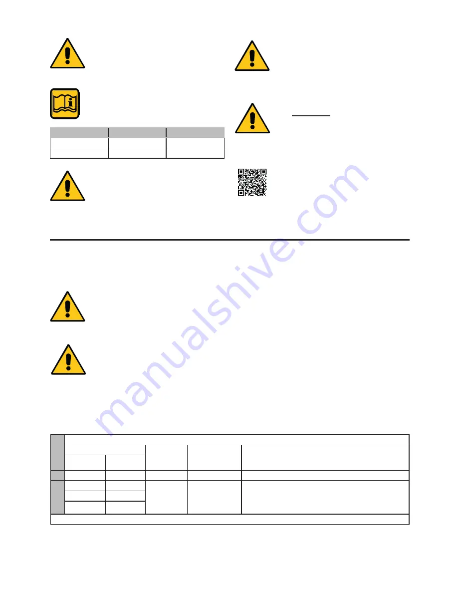
1.8 -  BOILER ANTIFREEZE  
 PROTECTION

It is activated by default 

VALuE

mIN 

mAX

PH

6.5

8

Hardness [°fr]

9

15

NotE!

Further details in the section 

‘‘technical Information’’ on the boiler

page of the www.unicalag.it website 

this protection can intervene only if the electricity 

and gas supplies are connected.

If one of the two is not available and upon reset 

11 (Sm) a temperature level between 2 and 

5°c is detected, the appliance will behave as 

described in the table below, pos 2.

the heating system can be protected effectively 

from frost by using antifreeze products with 

inhibitor for heating systems (specific for 

multidmetal)

do not use car engine antifreeze products as 

they could damage the water gaskets.

1.7 - wATER TREATMENT

Feed water treatment prevents problems and 

maintains the functionality and efficiency of the 

generator over time.

the ideal water pH in heating systems must be 

within:

to minimise corrosion, it is crucial to use a cor-

rosion inhibitor; in order for it to work properly, 

the metal surfaces must be clean. 

(see system protection AccESSoRIES sect. in 

domestic price list) 

P

O

S

ANTIFREEZE FUNCTION

 Power supplies

SM

 (*)

Status 

antifreeze func-

tion

Actions

Electric

Gas

1

oN

oN

< 7 °c

oN

- Burner and Pump oN until t > 15°c

2

oN

oFF

 < 5 ÷ 5 °c

oN

FAuLt SIGNAL codE 16 

(with Electrical power supply oN) 

(see par. 4.6  -  ERRoR codES).  

Ignition inhibited.

oFF

oN

oFF

oFF

(*) Flow sensor

Summary of Contents for SPK 150

Page 1: ...ENGLISH 150 230 300 400 500 600 INSTALLATION AND MAINTENANCE INSTRUCTIONS SPK ...

Page 2: ...t be disposed of as urban waste It can be taken to a special recycling centre managed by the local authorities or to a dealer who offers this service Separate disposal of a domestic appliance avoids possible negative consequences for the environment and human health deriving from inappropriate waste handling and allows the recovery of the materials of which it is made in order to obtain significan...

Page 3: ...3 11 2 Probes positioning 29 3 12 Checking burner pressure adjustment 29 Attention this manual contains instructions for the exclusive use of the professionally qualified installer and or maintenance technician in compliance with current legislation The user is NOT qualified to intervene on the boiler The manufacturer will not be held liable in case of damage to persons animals or objects resultin...

Page 4: ...al part of the product and must be kept by the user Read the warnings contained in this instruction booklet carefully as they provide important guidelines regarding installation use and maintenance safety Keep the booklet with care for further consultation Your appliance must be installed and serviced in compliance with the standards in force according to the manufacturer instructions up to standa...

Page 5: ...ppliance inserted in the envelope inside the packaging The user must keep this documentation safe for future consultation Inform the user about the importance of the air vents and the flue gas exhaust system highlighting their essential features and the absolute prohibition of modifying them Inform the user concerning controlling the system s water pressure as well as operations to restore it Info...

Page 6: ...ipe the safety valve and the exhaust pipe the construction parts which affect the operating safety of the appliance Attention To tighten or loosen the screwed fittings use only appropriate fixed spanners Incompliant use and or inappropriate tools can cause damage e g water or gas leakage ATTENTION Indications for propane gas fired appliances Make sure that the gas tank has been deaerated before in...

Page 7: ...approved flue gas exhaust configurations 8 NOx NOx Class A Heating circuit characteristics 9 Pn Effective nominal output 10 Pcond Effective output in condensation 11 Qn Maximum heat output 12 Adjusted Qn Adjusted for rated heat output 13 PMS Max heating operating pressure 14 T max Max heating temperature B Domestic hot water circuit characteristics 15 Qnw Rated heat output in domestic hot water fu...

Page 8: ... as described in the table below pos 2 The heating system can be protected effectively from frost by using antifreeze products with inhibitor for heating systems specific for multidmetal Do not use car engine antifreeze products as they could damage the water gaskets 1 7 WATER TREATMENT Feed water treatment prevents problems and maintains the functionality and efficiency of the generator over time...

Page 9: ...L FH VM Fan 19 AF AS PV Flue gas pressure switch 27 E RIL Detection electrode 28 E ACC Ignition electrode 32 Inlet flue inspection 33 Panel Board 53 PG Gas pressure switch SPK 150 54 Visual inspection glass 55 Door insulation 56 Stainless steel vertical smoke pipes with internal aluminium 57 Technical water tank 58 SL Level sensor 59 Condensate collection pan 60 Combustion chamber 61 Air gas mixer...

Page 10: ...5 6 1467 323 5 743 571 1579 1679 230 1092 954 141 846 120 277 43 1917 65 6 1557 356 775 630 1697 1768 300 1181 1036 144 910 100 303 200 1946 65 6 1618 353 790 635 1741 1796 400 1276 1152 124 996 100 326 200 2130 65 6 1712 390 820 698 1794 1974 500 1276 1152 124 996 100 326 200 2130 65 6 1712 390 820 698 1794 1974 600 1398 1256 142 1096 200 388 220 2206 65 6 1753 390 810 763 1863 2052 ...

Page 11: ... of Corridor Width Lc calculation required to handle the boiler SPK 150 L Boiler Width P Boiler Depth LcLc Corridor Width Lp Door Width 666 Cw 900 x 944 698 mm SPK BOILER DIMENSIONS WITHOUT ITS CASING mm P L H 150 917 655 1785 230 1027 795 1895 300 1134 845 1910 400 1258 965 2075 500 1258 965 2075 600 1313 1065 2186 ...

Page 12: ...OF INTERNAL ACCESS Default scale for models SPK 400 SPK 500 SPL 600 optional for models SPK 150 SPK 230 SPK 300 SPK 150 SPK 230 SPK 300 To remove the cover release the 2 springs refer to the part shown below 1 1 2 2 ...

Page 13: ...rate in l h Dt 8K 14 655 Maximum flow rate in l h Dt 15K 7 816 Requested rated output in l h Dt 20K 5 862 SPK 300 Maximum flow rate in l h Dt 8K 29 426 Maximum flow rate in l h Dt 15K 15 695 Requested rated output in l h Dt 20K 11 772 SPK 230 Maximum flow rate in l h Dt 8K 22 495 Maximum flow rate in l h Dt 15K 11 997 Requested rated output in l h Dt 20K 8 998 SPK 400 Maximum flow rate in l h Dt 8...

Page 14: ...emperature C 100 100 100 100 100 100 Maximum operating temperature C 85 85 85 85 85 85 Flue gas mass flow rate min kg h 56 16 80 97 105 26 107 0 131 5 141 7 Flue gas mass flow rate max kg h 224 60 346 57 453 47 621 05 728 67 898 97 Excess air 23 00 24 25 24 25 24 25 26 84 25 5 CO2 min max 9 3 9 3 9 2 9 2 9 2 9 2 9 1 9 1 9 2 9 2 9 1 9 1 Heat loss at chimney with burner on min 1 59 1 67 1 72 1 67 1 ...

Page 15: ...erature capacity Tr 30 C P1 kW 45 2 68 8 91 6 124 2 147 1 175 8 Performance at 30 of the rated heat output with low temperature capacity Tr 30 C ƞ1 96 9 96 6 98 2 98 1 98 2 96 0 Boiler with output range adjustment YES NO Auxiliary electricity consumption With a full load elmax kW 0 190 0 195 0 210 0 425 0 555 0 590 With a partial load elmin kW 0 042 0 040 0 032 0 051 0 053 0 088 Standby mode PSB k...

Page 16: ... hot water supply network compatible with its efficiency and output 3 1 GENERAL WARNINGS 3 2 STANDARDS FOR INSTALLATION It must be installed by a professionally qualified technician who shall take the responsibility of observing all local and or national laws published in the official journal as well as the applicable technical standards 3 3 PREVENTIVE VERIFICATION AND VERIFICATION AND ADJUSTMENT ...

Page 17: ...obe Cables output sheet metal SHC multifunction kit module Condensate drain siphon pipe 1 m 3 4 1 HANDLING The boiler must be handled by lifting it from the holes on the upper plate or using a transpallet If it is possible to program replacements you must provide for intervention with protective washing equipped with basic dispersant Washing must be carried out four weeks prior to replacement with...

Page 18: ...on ventilation suitable chimneys to drain combustion products from condensate boilers and anything else applicable When choosing the place of the installation of the appliance follow the safety instructions below Place the appliance in rooms protected from frost Avoid installation in rooms with a corrosive or very dusty atmosphere Comply with the minimum overall dimension dis tances in order to ex...

Page 19: ...ad Dp available at the base of the chimney HEAD AVAILABLE AT THE BASE OF THE CHIMNEY D Drain I Intake Dp 100 Pa The maximum permitted length of the pipes is determined by head Dp available at the base of the chimney B23P ATTENTION For this type of connection the room follows the same installation rules for boilers with natural draught Connection to a combustion products evacuation pipe outside the...

Page 20: ...use the optional accessories The boiler is equipped with is own draining valve Sc This valve can never be used to drain the system since all the dirt in the system can accumulate in the boiler and jeopardise its proper operation Therefore before using the drain valve make sure the system s check valve which is situated under the pump has been closed The system must be equipped with its own drain v...

Page 21: ...n intoxication hazard due to the release of exhaust gasses The connection between the appliance and the do mestic waste system must be made in compliance with the specific reference standards NOTE Further details in the section Technical Information on the boiler page of the www unicalag it website H Siphon head Capacity conditions 0 and Max Fan Head SPK 230 420 mm SPK 300 320 mm SPK 400 SPK 500 S...

Page 22: ...MPTYING THE SYSTEM When all system connections have been com pleted the circuit can be filled To fill the system you must provide a filling valve on the system s return EXAMPLE OF THE SYSTEM S LOADING UNIT UNIT OF LOADING ...

Page 23: ... heating controller Optional E8 Heating Controller 38 BMM Burner management board 39 M1 230 V Power Supply Terminals 1 2 43 BCM Boiler controller 44 F1 Power supply fuse 4 6 3 A 50 Power supplier board 51 TL Manually resettable limit thermostat 52 M2 Supplementary terminal 24V BCM 53 Power supply cable gland ...

Page 24: ... Remember that a bipolar switch must be installed on the boiler power line with over 3 mm between contacts easy to access making maintenance quick and safe Electric power supply connection TA connection Optional NOTE Further details in the section Technical Information on the boiler page of the www unicalag it website ATTENTION Size of power supply cables according to the boiler s power thus of ab...

Page 25: ... on terminal board BCM Y2 6 7 INAIL safety connections FL Flow switch connection Remove the jumper and connect the cables as indicated between Y2 11 and terminal board M2 Remove the jumper and connect the cables as indicated between Y2 10 and terminal board M2 Safety Connection ...

Page 26: ...l 230 V 50 Hz power supply NOTE The boiler is set up for direct flow and storage tank management If Stemp ACC is connected automatically DHW is activated which will have priority management with regard to direct flow through the pumps shown below Should additional services be requested storage If the storage tank temperature sensor is connected DHW service is automatically activated on boiler powe...

Page 27: ...ate valves open does the gas to be used correspond to the boiler calibration gas otherwise perform the boiler conversion in order to use the gas available see section 4 3 this operation must be carried out by technical staff qualified in compliance with the standards in force is the gas supply valve open has the system been checked for gas leaks is the outside main switch ON is the system safety v...

Page 28: ...bol 2 Calibration function SELECTION Set to using knob C and confirm by pressing A input the access code 3 MAXIMUM MINIMUM OUTPUT Set knob C to Confirm by pressing A it displays Set knob C to Confirm by pressing A Using knob C adjust the power to calibrate Press A to confirm MINIMUM OUTPUT MAXIMUM OUTPUT Calibrate each heating element by selecting the burners 4 DISABLING Upon calibration press B t...

Page 29: ...asurement of the flue gas temperature and content of CO2 taken in the relevant hole 2 Take the measurements with the generator in steady state conditions see par 3 11 1 2 Minimum output adjustment Operate the boiler in calibration mode at MINIMUM OUTPUT see 3 11 1 Once the burner is on check that the MINIMUM CO2 output value corresponds to what is indicated in the table NOZZLES PRESSURE If necessa...

Page 30: ...crease it see table NOZZLES CAPACITY PRESSURE 2 Minimum output adjustment Operate the boiler in calibration mode at MINIMUM OUTPUT see 3 11 1 Once the burner is on check that the MINIMUM CO2 output value corresponds to what is indicated in the table NOZZLES PRESSURE If necessary adjust the value by turning with a 2 5 mm hex key screw R CLOCKWISE to increase it ANTICLOCK WISE to decrease it see tab...

Page 31: ...ly system and drain power supply and drain pipes are not clogged 3 Conclusion of the basic calibrations once the CO2 values at minimum and maximum output have been checked and any adjustments have been made sections 1 2 disable the timed calibration function by switching off the main switch close the flue gas inspection sample points of the intake and exhaust terminal check that there are no gas l...

Page 32: ...bar mm mm min max FL FU FH FU min max IG Nat gas G20 20 18 12 3 32 76 9 1 9 1 45 Propane G31 37 18 6 0 36 69 10 8 10 8 45 SPK 500 Type of Gas Supply Press Ø Noz zlesi Opening VG Shutter Fan speed CO2 levels Furnace power mbar mm mm min max FL FU FH FU min max IG Nat gas G20 20 18 18 3 32 88 9 2 9 2 35 Propane G31 37 18 6 3 33 83 10 8 10 8 35 SPK 150 Type of Gas Supply Press Ø Noz zlesi Opening VG ...

Page 33: ...ginal spare parts are of the utmost importance for fault free operation of the boiler and to guarantee its long life Yearly maintenance of the appliance is mandatory in compliance with Laws in force Failure to perform Inspections and Maintenance can entail material and personal damage TABLE OF RESISTANCE VALUES ACCORDING TO THE TEMPERATURE OF THE HEATING PROBES 11 sr and any DOMESTIC HOT WATER pro...

Page 34: ...ck that it intervenes at 102 Condensation drain trap 27 Has the trap got deposits on the bottom Clean the trap with water Heat exchanger body If SL places the boiler in safety mode in the event of condensate level increases If PF places the boiler in safety mode in the event of flue gas exhaust clogging Check Remove any deposits in the combustion chamber using a vacuum cleaner then wash the heat e...

Page 35: ...SH D Provisionally secure the flanged curve 5 to the cover do not tighten the nuts completely 4 F Centre the burner between the electrodes keeping the same distance approximately 8 9 mm E Now completely secure the flange to the burner ...

Page 36: ... supplier or a person qualified in compliance with law If the tank has not been professionally deaer ated ignition problems could arise In that case contact the supplier of the LPG tank 4 3 ADAPTATION TO THE USE OF OTHER GAS Gas Conversion The boilers are produced for the type of gas specifically requested upon ordering Edit the parameters FH and FL max and min Fan speed for values see TABLE NOZZL...

Page 37: ... knob C and press A to access the technical program of each device requested password 0000 4 SELECTION Use knob C to select the parameter Press A selec 5 EDIT Turn knob C to edit the value Press A save 2 Device management SELECTION The screen displays the status and active system sections not active 1 active HCM Check the BCM cascade SHC optional multifunction module BMM burner management board Se...

Page 38: ... 486 FP Fan Reg Prop 0 50 30 30 25 25 25 25 487 FI Fan Reg Int 0 50 9 9 25 25 25 25 489 Fpl Fan PWM min 5 15 8 337 Fr Modulation Gradient 1 0 100 0 1 5 526 FU Fan Max Speed Hz 50 120 99 86 82 83 81 76 69 88 80 88 92 319 FH Maximum Modulation 1 0 100 0 100 346 FL Minimum Modulation 1 0 100 0 31 32 32 32 36 32 34 29 314 Sb Modulation on Standby 0 100 0 620 IP Postpurge Fan 0 100 65 617 IGL Ignition ...

Page 39: ...ustment 0 15 0 656 drT DHW Temp Requested Differential K 20 20 4 657 drH DHW Requested Temp Hysteresis K 1 20 8 310 DpT DHW Pump Postcirc sec 5 600 60 660 dbT DHW Temp Maximum Boiler C 50 0 85 0 75 0 48 ChSet CH 1 Set point C 20 0 85 0 85 0 64 ChPO1 CH 1 Parallel Supply 0 1 0 346 FL Minimum Modulation 0 100 0 25 0 600 mB Burners Min Inserted 1 8 1 616 BSt Gen Insertion Time sec 30 900 120 613 BRt ...

Page 40: ...Pump SM Flow sensor M2 Safety Terminal Board PF Flue gas pressure switch PF min Smoke pressure minimum pressure switch PG min Gas minimum pressure switch PG max Gas maximum pressure switch SL Condensate level sensor SM Flow Sensor T ACC 1 2 Ignition Transformation 1 2 TL Limit thermostat VG Gas valve VM A Modulating Fan Power Supply VM R Modulating Fan Det Adjustment SE External probe connection t...

Page 41: ...perature Sensor ANALOG INPUT Analogical input GND 0 10V ING Analogical input 0 10 V 0 10V C P M Modulating Pump Control ALARM SIGNAL Alarm Output Comm P COLL Boiler collector pump control Comm P CH Heating pump control P car DHW Storage tank loading pump control COM Common Optional or only for certain countries SM ...

Page 42: ...ing sensor fault Check the efficiency of the sensor see table Res Temp Par 4 or its connections 14 RETURN PROBE if present Auxiliary SRR sensor interrupted Check the wiring if needed replace the auxiliary sensor 22 15 INSUFFICIENT WATER CIRCULATION Primary circuit water circulation insuffi cient t 40 C Check pump operation and its speed remove any obstructions in the heating system 16 EXCHANGER FR...

Page 43: ...eturn t maximum pres sure stop effect Check circulation check installation only with a return probe present 19 Flow overtemperature It is activated when the flow temperature is 95 Resetting is automatically carried out when the temperature is 80 Effect Stop burner Pump On Circulation control 28 CLOGGED OUTLETS Stop Check the Chimneys Check the trap 29 WATER IN THE COMBUSTION CHAM BER Stop Check th...

Page 44: ...rmore it reserves the right to modify its products as deemed necessary or useful without affecting their essential features 46033 casteldario mantova Italy tel 39 0376 57001 telefax 39 0376 660556 info unical ag com export unical ag com www unical eu AG S p A 00335735 1 st Edition 08 15 www unical eu ...

Reviews: