18
Installation instructions
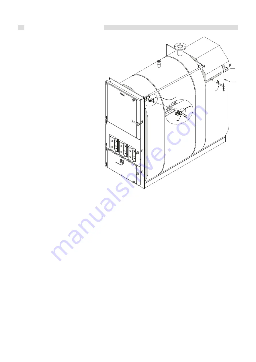
Assembling turbulator control lever
mechanism and microswitch
- Fit the extension of the turbulator cleaning lever mechanism
(pos. 1).
- Fit the microswitch (pos. 2) to the bracket making sure it
makes correct contact with the plate at the upper wood loading
door opening; adjust it if necessary.
Remember that the contact of the microswitch
must be normally open with the wood
loading door closed.
- The turbulator control lever and the knob
(pos. 3 and 4) must be fastened after the right
rear side casing has been assembled.
fig. 15
2
1
3
4
Assembling casing
- Fit the rear side panel support crosspiece (pos. 1) to the smoke
chamber.
- Position the side panels (pos. 3, 4, 5, and 6) on the boiler
body.
The panel with the hole is the one on the rear right.
- Fit the panel board (pos. 8) onto the front casing cover (pos.
7) with the finned nuts.
- Remove the cover of the electric control board, fix the board
on the upper panel (pos. 7) and pass the outgoing electric
cable of the fan and the thermostat capillaries (unrolling them
carefully) and the incoming electric cable of the door opening
microswitch, of the power line and of the pumps through the
middle hole of the panel.
Keep the electric cables from coming into contact with
the smoke chamber and/or parts of it or from being cut
by friction.
A silicon gasket to be fitted on the top part of the rear
plate of the boiler has been supplied in the accessory
box for this purpose.
- Place the casing cover (complete with panel board) on the
sides of the casing already mounted.
- Mount the two top rear panels (pos. 11 and 12).
- Place the bulb of the safety thermostat in the rear right bulb
holder (small conduit) fastening it with the fixing clip.
- Place the bulb of the flow probe (S4) in the rear left bulb holder
(large conduit) fastening the cable with the fixing clip.
- Insert the bulb of the return probe (S5) in the bulb holder on
the boiler return pipe (between the boiler and the recirculation
pump).
- Fit the bulb holder lg. 100 (supplied in the accessory bag) on
the specific attachment on the flue gas outlet pipe and insert
the flue gas probe inside.
Direct the thermocouple connection cable towards the panel
board and connected it as indicated on the wiring diagrams
associated to the hydraulic diagrams described on page 23;
pay the utmost attention that the metal sleeve (for the section
inside the panel board) does not come into contact with live
parts of the board.
For connection of the probes S1, S2, and S3, comply with that
indicated in the electric-hydraulic principle diagrams according
to the type of plant indicated on page 23.
- Fit the bottom back panel (pos. 13) to the casing.
- Fit the top back panel (pos. 14) to the casing.
Mount the cable clamps (pos. 15) on the back panel.
The electric wires coming out of the back of the boiler will be
connected with the specific cable gland terminals fixed on the
back panel, tightening them moderately.
- Perform the electrical connections as indicated in the wiring
diagrams described on page 23.
- Put the cover back on the electric control board.
- Fit the upper rear cover (pos. 16).
- Fit the turbulator control lever and the knob (pos. 17 and 18)
(pos. 3 and 4, fig. 15).
- Apply the boiler TECHNICAL DATA plate on the right side
of the casing after having cleaned the concerned area and
removed any grease with a suitable solvent.
Remove the protective film from the plate and apply it making
sure it sticks perfectly using a plastic spatula.
Do not remove the plate as it would no longer stick.


