background image

Quick Guide

UPO1000 Series

16/17

9.

Troubleshooting

(1)

When press the button, the oscilloscope is black screen.

a. Check whether the power is correctly connected, power supply is normal or not.
b. Check whether the power switch is really on, press the front panel power key and confirm green

light and a relay sound is present.

c. If there is a relay sound, it indicates that the oscilloscope starts normally. Try the following

operations: press the DEFAULT key, then press F1, if device returns to normal, it means backlight

brightness is too low.

d. After completing the above steps, restart the oscilloscope.

e.

If you still cannot use this product normally, please contact UNI-T.

(2)

After signal acquisition, the waveform of the signal does not appear in picture.

a. Check whether the two ends of BNC line are connected properly.
b.

Check

whether

the output channel of signal source is opened.

c.

Check

whether

the intput channel of the oscilloscope is opened.

d. Check whether the signal in signal source has DC offset.
e. Plug out the input signal, check whether the baseline is in the center of the screen (if the baseline

is not in the center of the screen, it should be self-calibration.)

f.

If you still cannot use this product normally, please contact UNI-T.

(3)

The measured voltage amplitude value is 10 times larger or 10 times smaller than the actual value:

Check whether the channel probe attenuation coefficient settings are consistent with the used probe

attenuation rate.

(4) There is a waveform display but not stable.

a. Check the trigger settings in trigger menu whether is consistent with the actual signal input

channel.

b. Check the trigger type: general signals should use “Edge” trigger. Only when the proper trigger

type is used, the waveform can be displayed stably.

c. Try to change trigger coupling to HF rejection or LF rejection to filter out he high-frequency or

low-frequency noise that interfere the trigger.

(5) No waveform display after press RUN/STOP key.

a. Check whether the trigger mode in the trigger menu is on “Normal” or “Single” and whether the

trigger level exceeds the waveform range.

b. If it exceeds, set the trigger level to the middle or set the mode to “Auto”.
c. The above settings can be completed automatically by pressing AUTO key.

(6) Waveform refresh is very slow.

a. Check whether the acquisition method is average and the average times are large.
b. Check whether the storage depth is the maximum.
c. Check whether the trigger hold-off time is greater.
d. Check whether the trigger is normal and the current time base is slow.
e. All he above reasons will lead to slow refresh of waveform. It is recommended to restore the

factory settings, and the waveform can be refreshed normally.

Summary of Contents for UPO1000 Series

Page 1: ...Quick Guide UPO1000 Series Digital Phosphor Oscilloscope...

Page 2: ...ts in China and foreign countries including issued and pending patents UNI T reserves the rights to any product specification and pricing changes UNI T reserves all rights Licensed software products a...

Page 3: ...eet the conditions stated in the Warning statement Caution Caution indicates the presence of a hazard It reminds users to pay attention to a certain operation process operation method or similar Produ...

Page 4: ...three phase distributor circuit includes a single commercial lighting circuit Fixed equipment such as multi phase motor and multi phase fuse box lighting equipment and lines inside large buildings mac...

Page 5: ...to release static electricity The protection grade of this device is 4KV for contact discharge and 8KV for air discharge Measurement accessories Measurement accessories are of lower class which are de...

Page 6: ...instrument is suitable for the following environment Indoor use Pollution degree 2 In operating altitude lower than 3000 meters in non operating altitude lower than 15000 meters Unless otherwise spec...

Page 7: ...ge may cause damage to component Components can be damaged invisibly by electrostatic discharge during transportation storage and use The following measure can reduce the damage of electrostatic disch...

Page 8: ...vel grayscale display The series is equipped with three levels of bandwidth of 50 MHz 100 MHz 200 MHz real time sampling rate up to 2 GSa s The whole series are equipped with 4 channels the maximum st...

Page 9: ...or replacement 3 2 Before Use To perform a quick verification of the instrument s normal operations please follow the steps below 1 Connecting to the Power Supply AC power specification of UPO1000 ser...

Page 10: ...ch to the probe Connecting the probe to the probe compensation signal connection clip and connecting the ground alligator clip to the ground terminal under the probe compensation signal connection cli...

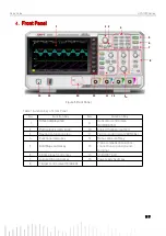
Page 11: ...se rotary knob 10 Analog channel input port 3 Navigation function area 11 Vertical control area VERTICAL 4 Functional menu key 12 Menu control soft key 5 Run Stop control key 13 Probe compensation sig...

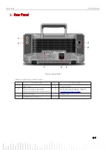
Page 12: ...l Table 1 Function Key of Rear Panel No Function Key No Function Key 1 EXT Trig 5 Power switch 2 AUX Out output port and arbitrary waveform signal output 6 AC Power input socket refer to Connecting Po...

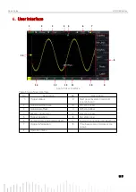
Page 13: ...time USB icon LAN icon 2 Horizontal time base 10 CH4 state label 3 Horizontal offset 11 CH3 state label 4 Waveform indicator 12 CH2 state label 5 Trigger position 13 CH1 state label 6 Sampling rate a...

Page 14: ...and adjust the parameter value represents the current menu have several options represents the current menu has a next menu represents use numerical keyboard to input the parameter represents the cur...

Page 15: ...can send the command via PC software to remote control the instrument It is recommended to use UNI T PC software instrument manager You can log in UNI T official website https www uni trend com to dow...

Page 16: ...The measured voltage amplitude value is 10 times larger or 10 times smaller than the actual value Check whether the channel probe attenuation coefficient settings are consistent with the used probe a...

Page 17: ...y to Friday or via email Our email address is infosh uni trend com cn For product support outside mainland China please contact your local UNI T distributor or sales center Many UNI T products have th...

Reviews: