background image

05 


Operation 

(14) This pump is not designed to be explosion-proof. When using the pump, ensure that there 

are no inflammable materials such as solvents, or explosive gases, in the vicinity. Use under 
such conditions may result in injury or fire. 

(15) Inserting fingers or objects into the motor inlet may result in electric shock, injury, or fire. 
(16) Operating the pump with the discharge outlet blocked, or with a device which prevents 

passage of gas to the discharge outlet, may result in rupture of the pump. The internal 
pressure of the pump rises and the pump body may rupture and the motor become 
overloaded. 


This pump is not designed to be pressure-resistant. The internal pressure of the pump is 
limited to 0.03 MPa (gauge pressure). 


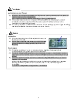
Maintenance and Repair 

(17) The pump should be dismantled or repaired only by a repair technician trained by the 

manufacturer. 

(18) To prevent ingestion of microscopic particles resulting from wear of components, use a dust 

mask and gloves during repair work. 


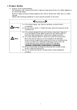
Installation 

(1)  The fine clearances used in this pump require that the following conditions be satisfied during 

storage, installation, and operation. 


1. 

Ambient temperature of 0~40°C and maximum relative humidity of 85% during operation. 


2. 

Other conditions for storage and operation. 


a)  Level floor of sufficient strength. 


b)  No condensation 


c)  Dust-free environment 


d)  Well ventilated 


e)  Environment free of corrosive or explosive gas. 


f) 

Not subject to direct sunlight. 


g)  No danger of fire. 


h)  Maximum ambient temperature of 40°C during assembly of pump. 

(2)  To prevent back injury, always use both hands to lift pumps. 
(3)  Microscopic particles resulting from wear of components are discharged from the outlet and 

contaminate the room. If necessary, connect a pipe from the discharge outlet to the outside of 
the building. 


Operation 

(4)  Do not use in applications involving organ transplants, or contact with body fluids or living 

tissue. 

(5)  Touching rotating components (eg motor, main shaft, axial joints, cooling fan) while the pump is 

in operation may result in injury. 

(6)  The overload protector operates when the pump becomes excessively hot. Touching it in this 

 condition may result in burns. 

(7)  Touching the motor while the pump is in operation or while it is still hot immediately after having 

been switched off may result in burns. 

(8)  Do not insert fingers or objects into, or peer into, the inlet or outlet during operation. 


!

Warning


!

Caution


Summary of Contents for DTC-41C

Page 1: ...nd effective use of the equipment Keep this manual in a safe place Due to periodic improvements in performance the equipment described in this manual is subject to changes in dimensions and specificat...

Page 2: ...Compressors and vacuum pumps Safety requirements Part2 Vacuum pumps IEC EN 61010 1 2010 A1 2019 Safety requirement for electrical equipment for measurement control and laboratory use Part1 General re...

Page 3: ...lated is in conformity with the following standards BS EN 1012 2 1996 A1 2009 Compressors and vacuum pumps Safety requirements Part2 Vacuum pumps BS IEC EN 61010 1 2010 A1 2019 Safety requirement for...

Page 4: ...allation 4 3 5 Piping 4 3 6 Storage 5 4 Cautions for Operation 5 4 1 Cautions for Operation 5 4 2 Operation of the Thermal Protection Relay 5 4 3 Starting in Cold Weather 5 5 Pump Performance 6 5 1 Pr...

Page 5: ...3 1 Example of Piping When discharging a Vessel 5 Table 1 1 Product Specifications 1 Table 1 2 Electrical capacity recommended value of protective devices 2 Table 6 1 Consumables List 7 Table 6 2 Loc...

Page 6: ...quipment correctly Read the section on Safe Use particularly closely Keep This Manual in a Safe Place After reading this manual be sure to keep it in a safe place which is readily accessible to others...

Page 7: ...the sales division of the manufacturer if there are any problems with the pump Customers purchasing the DTC 41K C D E F Do not grip or pull the tube on the top of the pump when removing it from the p...

Page 8: ...r medium injuries to the operator or damage to the equipment Incorrect handling of the equipment may result in damage to the equipment and hinder its correct operation Some components reach surface te...

Page 9: ...ve the power cord from the wall socket before checking or repairing the pump Failure to do so may result in electric shock or the pump suddenly starting and causing injury 5 Ensure that the relevant w...

Page 10: ...age installation and operation 1 Ambient temperature of 0 40 C and maximum relative humidity of 85 during operation 2 Other conditions for storage and operation a Level floor of sufficient strength b...

Page 11: ...to shocks or tipped over on its side 2 Do not hold or push the tube at the top of the pump see below Damage to the tube may affect performance of the pump Applications 3 This pump is exclusively used...

Page 12: ...se at high ambient temperatures will dramatically reduce the life of the pump 10 Back pressure at the outlet while the pump is starting may overload the motor 11 The thermal protection relay operates...

Page 13: ...ump is designed for general corrosion resistance however it is not resistant to molten alkali metals such as molten sodium to fluorine at high temperatures and to some oxides of fluorine 4 Corrosion r...

Page 14: ...that changed the power cord specification of DTC 41C to Power cord specification with plug for North America Other than the power cord specification it is the same as DTC 41C Product specification val...

Page 15: ...3 2 Dimensions Fig 2 1 DTC 41 C D E F Fig 2 2 DTC 41K C D E F...

Page 16: ...nti vibration rubbers to isolate the pump from vibrations in the equipment See 3 2 Environmental Conditions for Installation Storage and Operation for details 3 4 Checking Operation After Installation...

Page 17: ...the power cord from the outlet and contact the manufacturer Note that the pump will be very hot and should not be touched 2 The pump operates automatically when temperature drops Shut off the power su...

Page 18: ...eased pressure 2 Leaks into the vacuum system introduce other gases resulting in increased pressure 5 2 Discharge Rate The maximum rate of discharge is reached when air is introduced and decreases sli...

Page 19: ...er the first 3000 hours of operation and replace and clean in accordance with the Replacement and Cleaning Guide on the following page Refer to 6 4 Replacing and Cleaning Consumables for procedures Re...

Page 20: ...d Visual inspection O rings Hard cracked or stretched Visual inspection Bearings Abnormal noises Listen 6 4 Replacing and Cleaning Consumables See Caution 11 P06 Always use a mask and gloves when repl...

Page 21: ...ws M6 x 25 and remove the pump head as shown in Photo 4 Caution Gripping pushing or bending the connecting tube will damage it and reduce the performance of the pump Caution Lay the removed pump head...

Page 22: ...moving the diaphragms it is convenient to insert the pump head cover hexagon socket head cap screw M6 x 25 into the threaded hole in the connecting rod 8 Remove any foreign matter from the threaded ho...

Page 23: ...utlet pipes 1 2 DTC 41K C D E F Replace diaphragms in accordance with 1 1 DTC 41 C D E F steps 4 12 2 Replacing Inlet and Outlet Valves simultaneous replacement of both diaphragms is recommended Use t...

Page 24: ...he pump head from the casing and then remove the valve retainer in accordance with steps 1 and 2 in 2 Replacing inlet and outlet valves 2 Remove the O rings Photo 14 15 16 3 Clean the inlet and outlet...

Page 25: ...small for capacity of vacuum vessel 1 Select another pump 2 Pressure measurement is incorrect 2 Measure the pressure correctly 5 1 3 Vacuum gauge is unsuitable 3 Measure with a calibrated vacuum gaug...

Page 26: ...e and inspection etc d Malfunctions caused by modifications or repairs carried out by a party other than the manufacturer or by a service company not approved by the manufacturer e Malfunctions caused...

Page 27: ...Industrial Safety and Health Law designates particular substances as the materials to be notified 2 Usage Status Operation Method Approx hours per day years and months Continuous Operation Intermitte...

Page 28: ...6 6397 2286 ULVAC KIKO Inc https ulvac kiko com en Please contact us for products Service Base or other Inquiries from here ULVAC Inc Components Division 2500 Hagisono Chigasaki Kanagawa 253 8543 Japa...

Reviews: