8
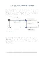
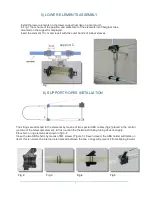
The two collars
A
and
B
are joined by a fiberglass rod (fig.6) that mechanically binds the upper to the lower
element, this is necessary to maintain the uniform geometry of the loop and at the same time it distributes the
string support to the lower element.
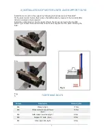
The fiberglass rod is fixed to the supports by means of one of the 4 locking bolts (page 9 - fig. C)
NOTE
: As mentioned in the "Standard" manual, there may exist small differences in length between the
elements and then between the junctions, for this reason it can happen that the bottom joint B is not perfectly
aligned with the upper, even if this is not of great importance, you can correct the alignment of the lower
coupling by adjusting the insertion of the lower element into the “C” support (page 7-fig.1). The space of 10
cm inside the tube holding of the elements is sufficient to compensate for any misalignment of the lower
support
B
.
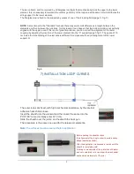
Fig.6
7) INSTALLATION LOOP CURVES
The outer loops are fixed, with high mechanical resistance, by the internal
adhesive heat shrink sleeve.
Insert the sheath into the element and then insert the same into the
PVC 180 °curve (normally enter 8-10 cm).
Slide the sheath over the joints, and heat with the heat gun
The procedure is the same one used for the telescopic elements.
Note:
the surfaces must be cleaned before application
Before heating the sheaths check
the alignment of the loop in order to avoid a candy
shape (aesthetics factor).
After the application it is necessary to wait until the
sheath is completely cold.
Twisting or movements of the joint when still warm
and not completely cold can impair the mechanical
seal and the waterproof of the joint.
A
B

