


WiMo Antennen und Elektronik GmbH
Am Gäxwald 14, D-76863 Herxheim Tel. (07276) 96680 FAX 9668-11
http://www.wimo.com e-mail: [email protected]
2
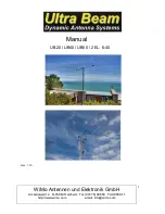
UB-50
Tape path
conductor
Driver
Driver
30-40
Fig.2
Introduction
Some UltraBeam models work in 30 and 40 meters band with folded elements, this allows you
to work on 30 and 40 meters with full-size elements in the same mechanical dimensions of
UltraBeam 6-20 models.
This technique has been applied on 2 and 3 element Yagi models.
In order to achieve that two curve models are applied to the ends of the elements, joined together
by glass fiber tubes, this creates a corridor in which the copper tape can scroll to reach the required
length for resonating up to 40 meters.
Figures 1 and 2 show in red the path and the shape of an inverted "C" which the folded dipole
looks like when operating on 40 meters.
NOTE: This manual only refers to the installation of the curves, side elements
and other specific parts of the models which work on 30m and 40m with folded
elements. For all other antenna assembly instructions refer to the manual
"Standard"
5
,4
m
.
2
elements
6-40
conductor
Driver
Driver
6-40
Fig.1
Single model driver
Double model driver
1,6m
5,1m


