


CF.440.400.001.IM.0417
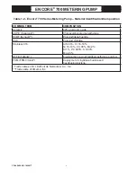
ENCORE
®
700 METERING PUMP
18
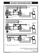
The Typical Installation drawings (Dwgs. 440.400.110.010, .020, .030, and
.040) and the associated wiring diagram (Dwg. 440.400.130.010) for the vari-
ous pump confi gurations are located at the end of this section.
NOTE: Some chemicals (such as sodium hypochlorite) emit gas and could
cause "air binding." Follow installation Dwg. 440.400.110.050 and consult
publication TA1055-A for additional tips.
Avoid operating problems by preventing the following:
• Unnecessary restrictions in piping
• Thin-walled hose, which may collapse due to a small cross-sectional area
during suction stroke, thereby causing both a high pressure drop and velocity
• Diffi
cult to vent bends in the line, where air may be trapped, impairing the
accuracy of feed rate
If a storage container is used, the suction line should be connected above the
container’s bottom to avoid any deposits on the bottom that can enter the suc-
tion line. Such deposits may damage the pump valves and impair the function
of the pump.
If the liquid to be pumped contains undissolved particles, install an adequately
dimensioned strainer (preferably one size larger than the pipe diameter) in the
suction line.
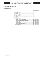
Summary of Contents for Encore 700
Page 2: ......
Page 3: ...ENCORE 700 DIAPHRAGM METERING PUMP MANUAL NO CF 440 400 001 IM 0417...
Page 6: ......
Page 8: ......
Page 16: ...CF 440 400 001 IM 0417 ENCORE 700 METERING PUMP...
Page 30: ...CF 440 400 001 IM 0417 ENCORE 700 METERING PUMP 14...
Page 70: ......
Page 124: ...CF 440 400 001 IM 0417 ENCORE 700 METERING PUMP 107...


