background image

02

03

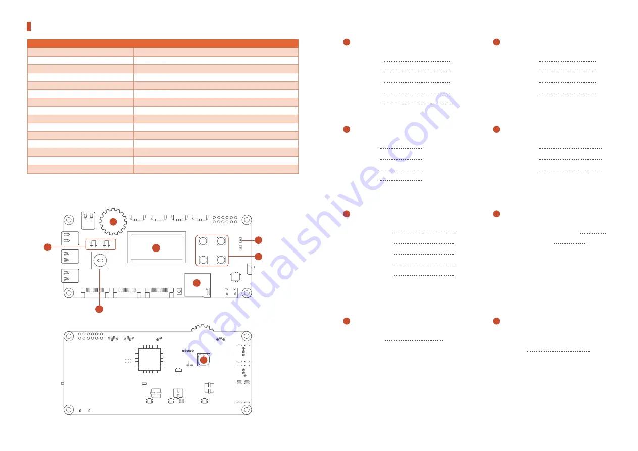
Hardware Parameters

128X64 Display Pin Description

LCD_CS

LCD_RES

LCD_CD

LCD_SCK

LCD_MOSI  

D 4 2

D 4 3

D 4 4

D 3 0

D 3 5

Micro SD Card Pin Description

TF_CS

TF_SCK

TF_MOSI

TF_MISO

D13

SCK(D53)

MOSI(D51)

MISO(D50)

RGB LED Pin Description

RGB_LED_R

RGB_LED_G

RGB_LED_B  

D 2

D 3

D 5

(Vil On, Vih Off, Controlled by Hardware PWM)

IIC Device Address

EEPROM 24C128 Address

ADXL345 Address

D13

SCK(D53)

BUTTON Pin Description

BUTTON_A

BUTTON_B

BUTTON_C

BUTTON_D

D 4 7

D 4 9

D 1 2

D 1 1

(Press Vil, Loosen Vih)

Buzzer Pin Description

BUZZER 

D 4 5

Rotary Potentiometer Pin 

Description

ROTARY

A 1 5

(Hardware PWM Control)

(Measurement Analog)

Joystick Pin Description

JOY_UP

JOY_DOWN

JOY_LEFT

JOY_RIGHT

JOY_CENTRE   

D 3 3

D 4 1

D 3 2

D 3 7

D 4 0

(Press Vil, Loosen Vih)

1

A

B

C

D

3

5

6

2

4

8

7

1

2

3

4

5

6

7

8

Specification


Weight 

0.15kg 

Dimension(L*W*H) 

150mm*132mm*281mm 

Connection with PC 

Micro USB 

Input Voltage 

USB 5V 


Main Controller 

ATMEGA2560 (Arduino compatible) 

Display 

128x64 OLED 

Buttons 

Rotary Potentionmeter 

TypeC 

4 (only for uarm connection) 

RGB LED 

Micro SD 

4P Connector 

2xDigital IOs / 2xIIC 

Extendable I/O 

6xdigital IOs 

Operation Temperature & Humidity 

0

-35

      30%RH-80%RH noncondensing 

Storage Temperature & Humidity 

-20

-60

      30%RH-80%RH noncondensing 


Summary of Contents for uArm Controller

Page 1: ...uArm Controller User Manual 2 0 1 8 1 2 2 8 V1 0 1...

Page 2: ...tentiometer 1 27mm 4P IIC IIC Digital Digital RGB LED Power Switch Button 4 USB Input Micro SD Card Slot Reset 128 64 OLED ADXL345 Joystick 128K EEPROM UART1 485 UART1 485 UART2 TTL UART3 TTL Type C 4...

Page 3: ...BUZZER D 4 5 Rotary Potentiometer Pin Description ROTARY A 1 5 Hardware PWM Control Measurement Analog Joystick Pin Description JOY_UP JOY_DOWN JOY_LEFT JOY_RIGHT JOY_CENTRE D 3 3 D 4 1 D 3 2 D 3 7 D...

Page 4: ...l Port a 1 27mm 4P cable should be purchased separately Note the four core TypeC cable in the market is not supported for this port please link it to the test point in the back Peripheral Port Pin Des...

Page 5: ...and the COM Port the COM Port is allocated randomly by your computer please use IDE for code writing or use Github routine code to develop 06 07 1 1 2 2 As shown in the following picture please press...

Page 6: ...ted with a computer please press the Reset button 08 09 For hardware connection please refer to Hardware Parameters Button Pin Description 1 Download Project File button_driver ino 2 Con gureArduinoID...

Page 7: ...File joystick_driver ino About how to download a single le from Github please refer to 3 Press the Upload button to upload rmware 4 Press the Serial Monitor button to open Port Assistant 2 Con gure Ar...

Page 8: ...ocated randomly by your computer please refer to the following picture 3 Press the Upload button to upload rmware 4 Test and the RGB light will alternates with red green and blue lights Note When uArm...

Page 9: ...he board as Arduino Genuino Mega or Mega 2560 Select the COM that allocated randomly by your computer please refer to the following picture 3 Open the Manage Libraries 4 Install u8glib 14 15 https git...

Page 10: ...2 TTL interface 2 Plug in the uArm Swift Pro 3 Connect the uArm Controller and Computer with USB 6 Check the Display Screen Scene Demo U g h t t p s w w w u f a c t o r y c c At the moment there is on...

Page 11: ...mware 9 Test and use the Joystick to control the movement of uArm i e move around use the rotary potentiometer to control the up and down motion of uArm press button C to adjust the speed press button...

Reviews: