Measuring Voltage
When taking voltage measurements your meter must be connected
in parallel to the circuit, or circuit element, under test. When the 1000 V
AC or DC function is selected the meter will automatically increase
its range form 400 volts with (0.1 - volt resolution) to 1000 volts (with
1-volt resolution) when the voltage measured exceeds 400. The
400-millivolt DC range allows you to use various adapters while the
1000-volt DC range allows you to measure most of the DC voltage
sources found in industrial applications.
WARNING!
Working with high voltage requires a greater awareness of physical
safety hazards. Before making live circuit tests, set the meter to the
desired function and range; connect the test leads to the meter first,
then to the circuit under test. Whenever possible, make test lead
connections when power is off then apply power to read the
measurement. If an erroneous reading is observed, disconnect power
immediately and recheck all settings and connections.
To measure AC or DC volts:
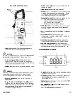
1. Set the rotary function select switch to the desired AC or DC
voltage position (Fig 1).
2. If measuring DC voltage, select the desired range.
3. Insert the test leads - Be sure your meter leads are firmly seated in
the meter’s jacks - Loose leads (or accessories) can cause readings to
fluctuate or allow less than the full signal into the meter.
4. Touch the test leads to the test points of the unit under test - The
black lead will ty p i cally be connected to the ground (or return)
terminal and red to the hot (or positive) terminal.
5. When measuring AC voltage, polarity is not critical - The accepted
p ractice (as a safety discipline) is to connect the black (common) lead
to ground or neutral and the red to the hot terminal.
6. The measured voltage will be displayed.
7. If the input on the red “
V
/
Ω
/ “ test lead is lower (more negative)
will appear on the left of the display.
8. If the test leads were attached to the circuit with power off,
disconnect power before removing them.
Measuring Resistance
WARNING!
Turn off power and discharge all capacitors on the circuit to be tested
before attempting “in circuit” resistance measurements. Failure to do so
may result in equipment or instrument damage. It is critical to both the
welfare of the meter, and the accuracy of the measurement, that you
remove all power to the circuit under test when making resistance
measurements. If any voltage is present in the test circuit, whether from
a conventional power supply, or energy stored in a capacitor, an erro-
neous reading will result. This meter may be damaged if more than
1000 volts are present.
NOTE:
• When measuring continuity or resistance, polarity does
not matter
• When measuring critically low ohm values, touch the tips of the
test leads together and re c o rd the test lead resistance value.
S u b t ract this value from the measured circuit’s resistance to
obtain the most accurate re a d i n g
To measure Resistance:
1. Set the rotary switch to the resistance function.
2. Select the desired range using the button on the side of the meter.
3. Insert the test leads - Be sure your meter leads are firmly seated in
the meter’s jacks - Loose leads can cause erroneous or
fluctuating readings.
4. Turn off power to the circuit under test and ensure there is no
residual voltage present from any source - Charged capacitors and
batteries used for data back-up will adversely affect accura cy.
5. Touch the probes to the test points and read the display - Be sure you
have good contact between the test leads and the circuit - Dirt, oil,
solder-flux or other foreign matter alters the reading value.
Measuring Continuity
Use the continuity mode “ “ to make quick checks for continuity in
circuits, such as electrical wiring, switch contacts, relays and audio
cables. in the continuity mode, an audible tone sounds when the value
measured is approximately 40
Ω
or less.
To test for continuity :
1. Set the rotary switch to the continuity function.
2. Place one probe to each side of the circuit to be tested - If
approximately 40
Ω
or less resistance is in the circuit, the meter
sounds a continuous tone - The resistance value (up to 400
Ω
) will
be displayed regardless of the continuity tone.
DL99B-MAN
P. 4
(Fig 1)


