background image

• If any of the following indications occur during testing, turn 

off the power source to the circuit under test:

• Arcing
• Flame
• Smoke
• Extreme Heat
• Smell of Burning Materials
• Discoloration or Melting of Components

• Read the safety precautions associated with the equipment being 

tested and seek assistance or advice when performing 
unfamiliar tasks.

• Keep your fingers away from the test lead metal probe contacts 

and bus-bars when making measurements. Always grip the 
instrument and test-leads behind the hand guards (molded into 
the probes).

• In the event of electrical shock, ALWAYS bring the victim to 

the emergency room for evaluation, regardless of the victim’s
apparent recovery. Electrical shock can cause an unstable heart
rhythm that may need medical attention.

International Symbols

L i s t i n g s

This instrument is designed and tested in accordance with:

IEC Publication 1010-1 (Overvoltage ca t e g o ry III), the safety requirements
for hand-held current clamps for electrical measurements and tests, the
EMC directive, and other safety standards.

Introduction

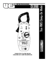
The D99B Digital Clamp-On Meter is designed for professional electrician's,
plant maintenance specialists and service technicians. Now technicians ca n
work with added confidence, knowing they’re measuring with the superior
a c c u ra cy of True RMS, increasing safety by illuminating dark work areas
with a bright LCD Work Light, back light display and extending their 
measurement capabilities to 1000V AC / D C .

Features include

• True RMS
• Work light and backlit display
• 1000 Amps AC and DC
• 1000 Volts AC and DC
• Resistance to 40 kilohms
• Continuity
• Push-button ranging
• Peak hold
• Data hold
• 0.1 mV DC resolution allows use of DMM adapters
• 1-3/8” jaw capacity
• CE and UL listed CAT III

Safety Notes

Before using this meter, read all safety information carefully. In 
this manual the word 

"WARNING"

is used to indicate conditions 

or actions that may pose physical hazards to the user. The word 

"CAUTION"

is used to indicate conditions or actions that may 

damage this instrument.

WARNING!

Exceeding the specified limits of this meter is dangerous and can
expose the user to serious or possibly fatal injury.

DO NOT

attempt to measure any voltage that exceeds 1000 volts 

DC or AC-RMS with this meter - UEi offers numerous alternatives
for measuring high voltage and current

• Voltages above 60 volts DC or 25 volts AC may constitute a 

serious shock hazard

DO NOT

attempt to use this meter if either the meter or the test 

leads have been damaged. Send unit in for repair by a qualified
repair facility

• Test leads must be fully inserted prior to taking measurements
• Always turn off power to a circuit (or assembly) under test before 

cutting, unsoldering or breaking the current path. Even small
amounts of current can be dangerous

• Always disconnect the live test lead before disconnecting the 

common test lead from a circuit

• When measuring high voltage, disconnect the power source before 

making test lead connections. Connect the test leads to the meter
first then to the circuit under test. Reapply power

DL99B-MAN    

P. 1

Summary of Contents for DL99B

Page 1: ...1 800 547 5740 Fax 503 643 6322 www ueitest com email info ueitest com DL99B INSTRUCTION MANUAL ...

Page 2: ...ment capabilities to 1000V AC DC Features include True RMS Work light and backlit display 1000 Amps AC and DC 1000 Volts AC and DC Resistance to 40 kilohms Continuity Push button ranging Peak hold Data hold 0 1 mV DC resolution allows use of DMM adapters 1 3 8 jaw capacity CE and UL listed CAT III Safety Notes Before using this meter read all safety information carefully In this manual the word WA...

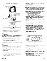
Page 3: ...C or DC current value recorded 2 Continuity Indicates the meter is in the continuity measurement mode and will sound a tone when measuring resistance below approximately 40 ohms 3 Hold Indicates the value displayed is frozen on screen the DATA HOL D push button is pressed 4 BAT Low Battery Indicator This symbol appears when the batteryneeds replacement Note A low battery will adversely affect accu...

Page 4: ...with the best possible resolution All other functions can be switched between one of the two available ranges by pressing the RANGE push button on the side of the meter The button is located where it can be accessed using your thumb allowing you to use just one hand to control the instrument Measuring Inductive Current The inductive current measurement mode relies on the induced electromagnetic fi...

Page 5: ...asuring Resistance WARNING Turn off power and discharge all capacitors on the circuit to be tested before attempting in circuit resistance measurements Failure to do so may result in equipment or instrument damage It is critical to both the welfare of the meter and the accuracy of the measurement that you remove all power to the circuit under test when making resistance measurements If any voltage...

Page 6: ...loth DO NOT use abrasives cleaning solvents or strong detergents as they may damage the finish or affect the reliability of the structural components Battery Replacement Always use a fresh replacement battery of the specified size and type Immediately remove the old or weak battery from the meter and dispose of it in accordance with your local disposal regulations Old or defective batteries can le...

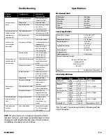
Page 7: ...Bad test lead connections Ensure test leads are fully inserted and free of corrosion or dirt DC Amps not zeroed Move meter away from power source and press DC or ZERO for 2 seconds Battery voltage Replace low battery Jaws are not closed tight Clean top and bottom mating surfaces of clamp jaws Meter reading is Rotary selector knob is offset Ensure knob is firmly unstable placed in switch position B...

Page 8: ...Standard Optional Accessories Standard Soft carrying case AC259 Test leads ATL55 Optional Plug in line splitter ASL1 Temperature measurement adapter TA2K Soft Carrying Case AC319 DL99B MAN P 7 ...

Page 9: ...mited to implied warranties of merchantability and fitness for a particular purpose are limited to the express warranty UEi shall not be liable for loss of use of the instrument or other incidental or consequential damages expenses or economic loss or for any claim or claims for such damage expenses or economic loss A purchase receipt or other proof of original purchase date will be required befor...

Reviews: