5.
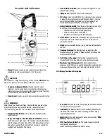
AC :
I n d i cates that alternating current (AC) amperage or voltage is
being measured.
6.
Minus:
I n d i cates the value measured has a negative polarity. This
will appear only while measuring DC amperage or voltage.
7.
DC:
I n d i cates that direct-current (DC) amperage or voltage is
being measured.
8.
mVA:
I n d i cates that millivolts (mV), volts (V), or amps (A) is
being displayed.
9.
K
Ω
:
I n d i cates that Kilohms, or ohms are being displayed.
10.
Numerical Value:
Displays the total value of the measured input.
Operating Instructions
Auto Power Off
This instrument automatically shuts off after 30 minutes of inactivity. The
meter is considered active when there is a change of at least 10 digits
during this period (i.e., the meter senses a change from 24.04 volts to
24.14 volts).
Rotary Function Select Switch
The rotary function select switch is used to select the measurement
mode and to turn the meter on and off. A long audible tone is heard
when the meter is turned on.
WARNING!
Set the rotary function select switch to the appropriate setting before
connecting the test leads to circuits under test. Observe the safety
practices outlined in the beginning of this manual.
Peak Hold
When measuring AC or DC amps you can use the “
PEAK HOLD
”
push-button at the top of the instrument to capture the highest
measured value. The word “
PEAK
” will appear along the top of the
display and the only the highest measured value will be displayed on
the LCD. Press the “
PEAK HOLD
” push-button a second time or
changing functions with the rotary function select switch will return
the instrument to the real-time measurement mode. An audible tone
is heard when this function is engaged or disengaged.
Data Hold
The “
DATA HOLD
” push-button freezes the reading displayed on the
LCD at the moment it is pressed. To engage data hold, press the “
DATA
HOLD
” push-button, located on the face of the instrument. When this
function is active, the symbol “
D.H
” appears on the digital display. To
cancel data hold, press the “
DATA HOLD
” push-button again, or select
any other measurement function using the rotary function select switch.
An audible tone is heard when this function is engaged or disengaged.
Selecting the Range and Resolution
Select the range and resolution you intend to use prior to preparing
equipment for measurement or touching test leads to measurement
points. All measurement functions offered on the DL99, except
continuity, have two ranges. An autorange feature has been built in to
the AC and DC volts functions to allow quick measurements of various
line voltages with the best possible resolution. All other functions.
can be switched between one of the two available ranges by pressing the
“
RA NGE
” push-button on the side of the meter. The button is loca t e d
where it can be accessed using your thumb, allowing you to use just one
hand to control the instrument.
Measuring Inductive Current
The inductive current measurement mode relies on the induced
electromagnetic field that occurs when electricity flows through a
conductor. Prepare your unit under test for measurement by separating
a single live conductor from any other phase, neutral or ground
conductor. Squeeze the clamp lever, place the conductor in the open
jaws then close the jaws around the conductor. To get the most accurate
reading, ensure the conductor is centered in the alignment marks and
the jaws are closed tight. The conductor must be able to fit inside the
1.25” (32 mm) fully open jaw.
To measure inductive AC current:
1. Place the function select switch in the 400/1000 Amp AC position.
2. Select the appropriate range using the button on the side - The
400 Amp range will display a decimal place while the 1000 Amp
range will not.
3. Place the clamp jaw around a single, live conductor.
4. Allow meter to stabilize - Observe reading.
NOTE:
The maximum limit for this function is 1000 amps AC. Too
much current will saturate the ferrous material in the clamp and
adversely affect accuracy.
To measure inductive DC current:
1. Place the function select switch in the 400/1000 Amp DC position.
2. Select the appropriate range using the button on the side - The
400 Amp range will display a decimal place while the 1000 Amp
range will not.
3. Place the clamp jaw around a single, live conductor - An arrow points
from the front of the meter toward the back to indicate the direction
of the positive terminal of the DC source.
4. Allow meter to stabilize - Observe reading.
NOTE:
The maximum limit for this function is 1000 amps DC. Too
much current will saturate the ferrous material in the clamp and
adversely affect accuracy. If DC current is measured over an
extended period of time the clamp may become difficult to zero.
Proper operation can sometimes be restored by rapidly opening
and closing the jaws or be temporarily reversing the meter’s
direction on the conductor (effectively reversing current flow).
WARNING!
Do not attempt to take any unknown voltage or current measurements
that may be in excess of this meter’s maximum limits. To avoid the risk
of electrical shock and instrument damage, open circuit voltage for the
circuit under test must not exceed 1000 volts AC or DC (RMS).
NOTE:
For all measurement requiring the use of the meter leads, insert
the red lead into the “
V
/
Ω
/ “ port and the black lead into the
“
COM
” port.
DL99B-MAN
P. 3


