background image

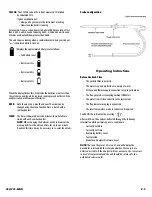
Analyzer Connections

NOTE:

Take care when inserting the temperature probes as the pins are

polarized. Insert with the smaller pin (+) to the right. A view of the
sockets is shown below

.

Automatic Calibration

During this sequence the analyzer pumps fresh air into the Oxygen and
CO (C75 only) sensors to allow them to be set to 20.9% and zero
respectively. See “Setting Inlet Temperature) for information on options.

Changing the Display

The parameters on the first line display are selected from the following
using the pump key (press and hold for display item to change). Certain
items are available on the lower display by selecting with the rotary dial.

*Available on the second line of the display.

C50/C75-MAN    

P. 3

Setting Inlet Temperature

During the automatic calibration sequence the burner INLET (Ti) 
temperature used in the NET temperature calculation is stored in the
analyzer. There are two methods of storing the INLET temperature.

A.  Without the flue probe connected temperature inside the analyzer 

is used (ambient temperature).

B.  If the flue probe is connected the temperature of the probe tip is 

used. This can be useful when the temperature of the air entering 
the burner is different than the ambient temperature of the room.

NOTE:

On ducted inlets, insert the probe tip into the inlet air during the

zero countdown. The analyzer will then store this temperature as the
ambient (inlet) for use in efficiency calculations. Do not sample flue gas
during the zero countdown.

WARNING!

If the INLET temperature is set incorrectly, then errors will be made in
the calculation of net temperature and efficiently.

Sampling the Flue Gas

Once the automatic calibration procedure has been completed and the
specific fuel has been selected (see menu options) the probe can be
inserted into the desired sampling point.

It is recommended that the sampling point be located at least two flue
diameters downstream of any bend, as close to the source as possible,
and that the probe tip is in the center of the flue. With balanced flues
and other domestic units the probe should be positioned far enough
into the flue so that no air can “back flush” into the probe.

The probe depth stop cone provided with the instrument allows the
probe to be used in holes whose diameters range from 1/4 to 4/5 inch
(6 mm to 21 mm).

The standard probe is rated at 1112˚F (600˚C).

TIP:

To conserve battery power, switch off the pump when you are not

taking a measurement. To turn pump ON or OFF press “            “.

View data and rotate the dial to see flue changes as you make 
adjustments. Press “

HOLD

” first to freeze or store the readings 

before printing.

Display

Item

Note

NAT GAS*

Fuel selected

Fuel indicator
• NAT Gas

Natural Gas

• Propane
• Butane
• L Oil

Light Oil

• LPG

Liquid Petroleum Gas

R 0.0000

CO/CO2 ratio

Measured CO divided by calculated CO2

P 0.00

Poison index

CO/CO2 ratio x 100

AMB xx

Ambient temperature

Either instrument internal temperature or

(used as inlet 

stored inlet temperature set during zero

temperature for 

T)

countdown

COa

CO air free reading

CO reading adjusted to 0% O2 (C75 only)

O2

O2 Ref

O2% reference value to calculate readings 
normalized to a set O2 level.

hh:mm:ss*

Time

Currently set time

MM/DD/YY*

Date

Currently set date

CO2*

Carbon Dioxide

Calculated CO2 value

O2*

Oxygen

Measured O2 value

T*

T Nett

Difference between Flue Temp and Ambient
(or inlet temperature)

TF*

T Flue

Measured Flue Temperature

η

(G, N or C)*

Efficiency

Displays calculated efficiency when O

2

values are less than 18%. Displayed as

η

N, 

η

G or 

η

C as selected by the user.

Losses (C50 only)

Losses calculated from Oxygen and type of
fuel. Displays reading during a combustion
test. “----” is displayed while in fresh air.

CO*

Carbon Monoxide

Displays Carbon monoxide values in PPM as

(C75 only)

CO. Display value in mg/m

3

as COm.

*

Battery level

λ

*

Excess Air

Flue (Tf) temperature
socket

Mains adapter socket

Flue gas inlet

Water trap drain plug

Summary of Contents for C50

Page 1: ...C50 C75 INSTRUCTION MANUAL 99 Washington Street Melrose MA 02176 Phone 781 665 1400 Toll Free 1 800 517 8431 Visit us at www TestEquipmentDepot com ...

Page 2: ...ON and OFF Hold to scroll through top line display also selectable through menu 6 Hold Store Freezes reading on display Entire display flashes Press and hold for 2 seconds to store data in memory 7 Rotary Selector 8 Particle Filter 9 Water Trap 10 Analyzer Connections Main Display Parameters O2 Oxygen reading in percentage Tf Temperature is measured by the flue gas probe in Centigrade or Fahrenhei...

Page 3: ...is the ratio of measured CO divided by calculated CO2 It gives an indication of How good a gas sample the instrument is reading How clean the boiler is running For example A new or clean domestic boiler will display a ratio of less than 0 004 a unit in need of cleaning 0 004 0 008 and a unit in need of major overhaul will show greater than 0 008 This only shows a reading when a combustion test is ...

Page 4: ... sampling point be located at least two flue diameters downstream of any bend as close to the source as possible and that the probe tip is in the center of the flue With balanced flues and other domestic units the probe should be positioned far enough into the flue so that no air can back flush into the probe The probe depth stop cone provided with the instrument allows the probe to be used in hol...

Page 5: ...e above the function keys The three keys are increases decrease and enter Set Time 1 Press ENTER 2 Use the up and down keys to select the correct time 3 Press ENTER to move to the next digit Note Time is displayed in military format example 7 00 pm is 19 00 Date 1 Press ENTER 2 Select desired format for the date display MM DD YY for month day year YY MM DD for year month day DD MM YY for day month...

Page 6: ...STORE view mode the rotary dial is used to select the saved parameter to be displayed Use the UP DOWN keys to change the test number To exit the view mode press ENTER Storing Test Results At any time during a test you may store the readings in one of the 1 memory positions Press and hold for 2 seconds or more Printing Information Supplied as an accessory for the analyzer is an infrared thermal pri...

Page 7: ...r x 2488 2 1 Tf 4 2 Ti Simplified 9 x H2 H2O Qgr x 2425 x 1 0 001 Tnet Wet loss K3 1 0 001 x Tnet Where K3 9 x H2 H2O Qgr x 2425 Combustion Combustion Theory In its simplest form combustion is the combining of oxygen O2 from the air with hydrogen H and carbon C from the fuel to form carbon dioxide CO2 water H2O and energy light and heat Perfect combustion occurs when all of the carbon and hydrogen...

Page 8: ...ir free In the example we would be breaking the limit and corrective action should be taken to reduce the level of CO Air free values prevent false readings being submitted e g allowing more air into the boiler will increase the oxygen level in the flue and dilute any toxic gas reading Air free referencing gives readings as if they were undiluted What Does Oxygen Reference Mean Oxygen referencing ...

Page 9: ...k Slide outward Pull plug out to drain Insert a new filter Maintenance Periodic Service WARNING Repair and service of this instrument is to be performed by qualified personnel only Improper repair or service could result in physical degradation of the instrument This could alter the protection from personal injury this meter provides to the operator Perform only those maintenance tasks that you ar...

Page 10: ... 10 V AC off load Annual Re Calibration While the sensor has an expected life of more than two years in normal use it is recommended that the analyzer is re calibrated at least annually This is so that long term drift on the sensor and electronics can be eliminated local regulations may require more frequent re calibration and users should check with appropriate authorities to ensure the comply wi...

Page 11: ...ited to implied warranties of merchantability and fitness for a particular purpose are limited to the express warranty UEi shall not be liable for loss of use of the instrument or other incidental or consequential damages expenses or economic loss or for any claim or claims for such damage expenses or economic loss A purchase receipt or other proof of original purchase date will be required before...

Reviews: