10
8. Liquid Saturation temperature.
9. Time: (HH:MM) Test Duration. Time starts counting as soon as Analyzer is powered on.
Time (Test Duration) resets to zero when Pressure Test button is pressed. Time resets
to zero when Pressure Test mode is exited.
10. T-High.
11. Subcool.
12. ∆T (Delta temperature): Displayed numerically to right of ∆T.
• Unit of measurement.
• Temperature Scale.
• Low Side Relative Pressure Bargraph: Each segment is 0.25 psi.
• High Side Relative Pressure Bargraph: Each segment is 1.0 psi.
- The Relative Bargraph shows real time changes in pressure. The center bar is stable.
If the pressure is increasing, the bars will go to right. If the pressure is decreasing,
the bars will go to the left.
• Backlight: Backlight will stay on until turned off.
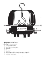
C. Power Button (Green):
• Press and hold to turn on analyzer. Press briefly when analyzer is on to turn on Backlight.
Press briefly to turn off Backlight. Press and Hold to turn analyzer off.
• Auto power off after 30 minutes.
D. Units Button:
Changes unit of measurement for pressure and temperature scale.
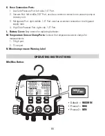
E. Min/Max Button:
• Used to Capture Maximum and Minimum values.
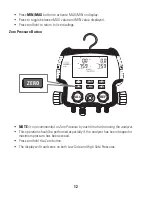
F. Zero Button:
Used to zero analyzer and compensate for ambient pressure changes or
sensor drift.
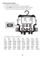
G. Refrigerant Button:
Used to select desired refrigerant.
H. Pressure Test Button:
Used to start and stop pressure test.
I. Site Glass:
Monitor refrigerant flow.
J. Flow Valves:
1. Low Side Flow Valve (Blue): Controls flow through low side port.
2. Vacuum Flow Valve (Yellow): Controls the flow through the vacuum port.
3. Refrigerant Flow Valve (Green): Controls flow through the refrigerant port.
4. High Side Flow Valve (Red): Controls flow through high side port.


