background image

15

Pressure Test/∆P (Delta Pressure) Button

• 

NOTE:


see diagram (page 19) – Connecting AK940 in Operating Instructions.

• Connect the analyzer to the system.
•  Select appropriate refrigerant.

•  Press Pressure Test button to start pressure test. Press again to stop pressure test.
•  When 

Pressure Test

 button is pressed, Start Pressure will appear on left side 

of display (where Low Pressure appears); When Pressure Test button is 
pressed again, End Pressure appears on the right side of the screen (where 
High Pressure appears).

•  Press and hold to return to live readings.


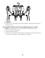
WARNING:


Maximum Pressure Range: 

725 psi

WARNING:


Proof Pressure: 

1000 psi

WARNING:


Burst Pressure: 

1500 psi

While in Pressure Test mode the following options are not available:
• Unit Selection
• Refrigerant Selection
• Min/Max mode
• Superheat and Subcool

VAC

REF

UNITS

MIN MAX

REF

ZERO

PRS TEST

Digital Refrigerant Analyzer

AK940

Psi

ºF

START

VAPOR SAT

PRS

END

LIQUID SAT

PRS

PRS TEST

Summary of Contents for AK940

Page 1: ...END PRS LIQUID SAT T HIGH SUBCOOL C F C F C F MAXMIN VAPOR SAT R P TIME Psi kPa Bar MPa T LOW SUPERHEAT T INSTRUCTION MANUAL ENGLISH AK940 Digital Refrigerant System Analyzer 99 Washington Street Melrose MA 02176 Phone 781 665 1400 Toll Free 1 800 517 8431 Visit us at www TestEquipmentDepot com ...

Page 2: ...Pressure Button 12 Refrigerant Selection Button 13 Unit Selection Button 14 Pressure Test P Delta Pressure Button 15 Superheat and Subcool 16 Vapor Liquid Saturation Temperatures 17 T Low and T High T Delta Temperature 17 18 Recovering Refrigerant Evacuating a System Adding Refrigerant to a System 18 Connecting AK940 19 Battery Replacement 19 DISPOSAL 20 CLEANING 20 STORAGE 20 WARRANTY 20 ...

Page 3: ...in 12 Parameter Backlit display Reads in Psi kPa Bar Mpa Bargraph Relative Zero to recalibrate 64 Refrigerant options Selectable F or C Over molded grip Thermistor temperature ports GENERAL SPECIFICATIONS Operating Temperature 4 to 122 F 20 to 50 C Storage Temperature 4 to 122 F 20 to 50 C Dimensions 7 3 4 X 7 1 2 X 3 1 2 Item Weight 2 97 lbs Calibration Recommended annually Battery Type 9V X 1 ...

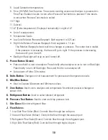
Page 4: ...elected 10 Time HH MM Test Duration 11 P Delta pressure 12 T Delta temperature Unit of Measurement Low Side Relative Pressure Bargraph Each segment is 0 25 Psi High Side Relative Pressure Bargraph Each segment is 1 0 Psi The Relative Bargraph shows real time changes in pressure The center bar is stable If the pressure is increasing the bars will go to right If the pressure is decreasing the bars w...

Page 5: ...ervice batteries around explosive gas vapor or dust Various refrigerants have been intentionally excluded for very significant reasons Never use refrigerants in this analyzer that are not listed in the Refrigerant Selection menu or Operating Instructions The refrigerant database in this analyzer may include refrigerants classified as flammable If such refrigerants are selected the operator may nee...

Page 6: ...rmanent damage Do not utilize any hose other than those supplied with the analyzer or supplied by UEi The use of other hose types will introduce errors into the refrigerant analysis and instrument calibration Never obstruct the air intake sample exhaust or case vent ports of the analyzer during use WARNING The analyzer contains no internal user serviceable parts other than batteries that may be ac...

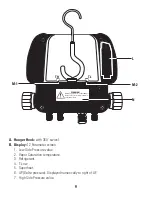
Page 7: ...tection Recommended High Voltage Risk OVERVIEW VAC REF UNITS MIN MAX REF ZERO PRS TEST Digital Refrigerant Analyzer AK940 LOW START PRS HIGH END PRS LIQUID SAT T HIGH SUBCOOL C F C F C F MAXMIN VAPOR SAT R P TIME Psi kPa Bar MPa T LOW SUPERHEAT T A C F I J 1 J 4 J 2 B 2 B 5 B 6 J 3 D G E H B 1 B B 3 B 7 B 8 B 9 B 10 B 11 B 12 B 4 K 1 K 3 K 2 K 4 ...

Page 8: ...ssure value 2 Vapor Saturation temperature 3 Refrigerant 4 T Low 5 Superheat 6 P Delta pressure Displayed numerically to right of P 7 High Side Pressure value TL WARNING DO NOT apply pressure above 600 psi Doing so may result in injury and will void the warranty TH L N M 1 M 2 ...

Page 9: ...ay on until turned off C Power Button Green Press and hold to turn on analyzer Press briefly when analyzer is on to turn on Backlight Press briefly to turn off Backlight Press and Hold to turn analyzer off Auto power off after 30 minutes D Units Button Changes unit of measurement for pressure and temperature scale E Min Max Button Used to Capture Maximum and Minimum values F Zero Button Used to ze...

Page 10: ...de 1 4 Port L Battery Cover Easy access for replacing batteries M Temperature Sensor Clamp Ports Connect the temperature sensor clamps for measurements 1 T High port 2 T Low port N Maximum pressure Warning label OPERATING INSTRUCTIONS Min Max Button VAC REF UNITS MIN MAX REF ZERO PRS TEST Digital Refrigerant Analyzer AK940 LOW START PRS HIGH END PRS LIQUID SAT T HIGH SUBCOOL C F C F C F MAXMIN VAP...

Page 11: ...ed to Zero Pressure by each time before using the analyzer This operation should be performed especially if the analyzer has been dropped or maximum pressure has been exceed Press and hold the Zero button The display will read zeros on both Low Side and High Side Pressures VAC REF UNITS MIN MAX REF ZERO PRS TEST Digital Refrigerant Analyzer AK940 Psi ºF LOW VAPOR SAT PRS HIGH LIQUID SAT PRS ZERO ...

Page 12: ...nalyzer R11 R12 R13 R14 R21 R22 R23 R32 R41 R114 R115 R123 R124 R134A R143A R176 R218 R236EA R236FA R245CA R290 R401A R401b R401C R402A R402b R403A R403b R404A R406A R407A R407b R407C R408A R409A R410A R410b R411b R412A R413A R414A R416A R417A R420A R421A R422A R422b R422d R423A R424A R427A R434A R437A R438A R501 R502 R503 R504 R507 R600A R601 R601A R718 R1234yF VAC REF UNITS MIN MAX REF ZERO PRS ...

Page 13: ...analyzer in order displayed Degree F Psi Degree F kPa Degree F Bar Degree F MPa Degree C Psi Degree C kPa Degree C Bar Degree C MPa Selecting the Scale Fahrenheit or Celsius will display for Vapor and Liquid Saturation temperature T Low and T High and T VAC REF UNITS MIN MAX REF ZERO PRS TEST Digital Refrigerant Analyzer AK940 LOW START PRS HIGH END PRS LIQUID SAT T HIGH SUBCOOL C F C F C F MAXMIN...

Page 14: ...w Pressure appears When Pressure Test button is pressed again End Pressure appears on the right side of the screen where High Pressure appears Press and hold to return to live readings WARNING Maximum Pressure Range 725 psi WARNING Proof Pressure 1000 psi WARNING Burst Pressure 1500 psi While in Pressure Test mode the following options are not available Unit Selection Refrigerant Selection Min Max...

Page 15: ... the system or making any adjustments to the system wait 15 minutes before charging by superheat or subcool to ensure the system is running correctly To add or remove refrigerant follow charging or recovery practices from manufacturer over those in this manual Let system stabilize for 15 minutes NOTE If subcooling or superheat is calculated to be negative the AK940 displays to indicate a problem i...

Page 16: ...m page 19 Connecting AK940 in Operating Instructions Connect analyzer to the system Select appropriate refrigerant Attach the Low Side temperature sensor clamp on the suction line between the evaporator and the compressor Attach the High Side temperature sensor clamp on the liquid line between the condenser and the expansion valve TXV Displays T Low and T High and T VAC REF UNITS MIN MAX REF ZERO ...

Page 17: ...Operating Instructions Connect the analyzer to the system Select appropriate refrigerant To add or remove refrigerant follow charging or recovery practices from manufacturer over those in this manual Let system stabilize for 15 minutes VAC REF UNITS MIN MAX REF ZERO PRS TEST Digital Refrigerant Analyzer AK940 LOW START PRS HIGH END PRS LIQUID SAT T HIGH SUBCOOL C F C F C F VAPOR SAT R P TIME Psi k...

Page 18: ... HIGH SUBCOOL C F C F C F VAPOR SAT R P TIME Psi kPa Bar MPa InHg T LOW SUPERHEAT T Blue 1 4 3 8 Yellow 1 4 Red 1 4 A Low Side Temperature Sensor Clamp Input Port B Low Side Pressure Hose Connection Port C Vacuum Hose Port D Vacuum Pump E Recovery Unit F Condenser Unit G Compressor H Suction Service Port I Low Side Temperature Sensor Clamp J Low Side Refrigerant Line K High Side Temperature Sensor...

Page 19: ...d your instrument should become inoperative from such defects the unit will be repaired or replaced at UEi s option This warranty covers normal use and does not cover damage which occurs in shipment or failure which results from alteration tampering accident misuse abuse neglect or improper maintenance Batteries and consequential damage resulting from failed batteries are not covered by warranty A...

Reviews: