Doc. 86371S - Rev. 01/02/2021
USER MANUAL
USER MANUAL
EN
EN
Drw. / Dis. 37304
22/43
MANUALE D’ISTRUZIONI
MANUALE D’ISTRUZIONI
IT
IT
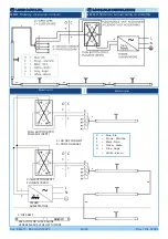
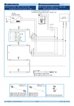
8.2.6 Customized cable wiring
8.2.6 Collegamento cavo personalizzato
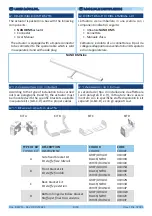
The 8-pin connector allows the enabling of the
actuator functions.
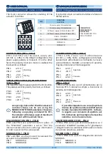
POWER SUPPLY (PIN 1 - PIN 2)
PIN 1 and PIN 2 are the power supply pins
(24 Vdc +/- 10%). In the default configuration, the
power supply polarity is irrelevant. If, on the other
hand, the polarity inversion mode is enabled, the
input works as follows:
PIN 1
+24 V
PIN 2
-24 V
PIN 1
-24 V
PIN 2
+24 V
Opening
t
t
Closing
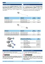
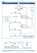
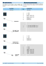
CONNECTION
BETWEEN TWO
ACTUATORS
COLLEGAMENTO TRA
DUE ATTUATORI
C= CHIUDE - CLOSE - FERME
ZU - CIERRE
ACCESSORI "UCS" ACQUISTABILI
PURCHASABLE "UCS" ACCESSORIES
ACCESSOIRES "UCS" ACHETABLES
ZUBEHÖRTEILE "UCS"
ACCESORIOS "UCS" COMPRABLES
A= APRE - OPEN - OUVRE
AUF - APERTURA
PULSANTE (DPDT)
PUSH BUTTON (DPDT)
BOUTON POUSSUAR (DPDT)
DRUCKNOPF (DPDT)
PULSADOR (DPDT)
M
L
I
H
E H
F
D
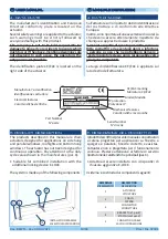
PIN
FUNCTION
FUNZIONE
1
Power supply /
Alimentazione
2
Power supply /
Alimentazione
3
SV Power supply /
Alimentazione EFC
4
SV Power supply /
Alimentazione EFC
5
CAN H - SYNCHRO
6
CAN L - SYNCHRO
7
MODBUS A
8
MODBUS B
2 4 6 8
1 3 5 7
Il connettore 8 pin consente di abilitare le funzioni
dell’attuatore.
ALIMENTAZIONE (PIN 1 - PIN 2)
I PIN 1 e PIN 2 sono i pin di alimentazione
(24 Vdc +/- 10%). Nella configurazione di default,
la polarità di alimentazione è ininfluente. Se invece
viene abilitata la modalità a inversione di polarità,
l’ingresso funziona nel modo seguente:
PIN 1
+24 V
PIN 2
-24 V
PIN 1
-24 V
PIN 2
+24 V
Apertura
t
t
Chiusura
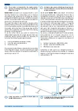
SMOKE VENTILATION (SV) POWER SUPPLY
(PIN 3 - PIN 4)
PIN 3 and PIN 4 are the power pins for the SV function.
They always work by polarity inversion, as follows:
PIN 3
+24 V
PIN 4
-24 V
PIN 3
-24 V
PIN 4
+24 V
Opening
t
t
Closing
ALIMENTAZIONE EFC
(PIN 3 - PIN 4)
I PIN 3 e PIN 4 sono i pin di alimentazione per la
funzione EFC. Funzionano sempre a inversione di
polarità, nel modo seguente:
PIN 3
+24 V
PIN 4
-24 V
PIN 3
-24 V
PIN 4
+24 V
Apertura
t
t
Chiusura
E’ possibile impostare una corsa di apertura
diversa da quella nominale dell’attuatore
tramite il parametro CORSA EFC. Tuttavia,
in seguito a un comando di apertura per
EFC, l’attuatore aprirà sempre alla massima
velocità e con la massima forza.
An opening stroke other than the actuator’s
nominal stroke can be set, using the
SMOKE VENT STROKE parameter. However,
following an opening command for EFC,
the actuator will always open at maximum
speed and with maximum force.
SYNCHRONIZATION (PIN 5 - PIN 6)
PIN5 and PIN6 are synchronization poles; if
the “SYNCHRO” parameter is set to “YES” the
interconnected actuators exchange information
in order to work at the same speed.
SINCRONIZZAZIONE (PIN 5 - PIN 6)
I PIN5 e PIN6 sono i poli di sincronizzazione; se il
parametro “SYNCHRO” è settato su “SI”, gli attuatori
collegati insieme si scambiano informazioni in modo
da lavorare alla stessa velocità.
MODBUS (PIN 7 - PIN 8)
PIN7 and PIN8 are the pin used to ceoonect the
actuatot to tne MODBUS network.
PIN 7
MODBUS A
PIN 8
MODBUS B
MODBUS (PIN 7 - PIN 8)
I PIN7 e PIN8 sono i poli di collegamento alla rete
MODBUS.
PIN 7
MODBUS A
PIN 8
MODBUS B

