ODIN-W2 series - System integration manual
UBX-14040040 - R20
System description
Page 13 of 43
C1-Public
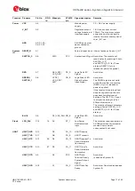
Function Pin name
Pin No.
GPIO
id
Mbed pin
STM32
pin
Signal description
Remarks
JTAG_TCK
TP9
JTAG_TCK
PA_14
JTAG not used for u-blox
connectivity software
JTAG_TDO
TP10
JTAG_TDO
PB_3
JTAG not used for u-blox
connectivity software
SYS_BOOT
TP11
SYS_BOOT
BOOT0
Pull to V_INT to
enter the ROM
based bootloader
10k internal pull down
RSVD
TP1, TP2,
TP3, TP4,
TP6, TP12
Reserved pin.
All RSVD should be left
unconnected.
Table 2: ODIN-W2 pin description
⚠
Do not apply any Voltage to Digital, Control and Radio signal groups while in Not Powered mode to
avoid damaging the module.
1.3
Supply interfaces
1.3.1
Main supply inputs
The ODIN-W2 series modules must be supplied with a DC power through VCC pins. Voltage must be
stable, as during operation, the current drawn from the VCC can vary significantly depending on the
power consumption profile of the Bluetooth (BT) and Wi-Fi technologies. See Supply interfaces
section for power supply design information and the
ODIN-W2 series Data sheet [2] for information
about voltage supply requirement.
Rail
Voltage requirement
Current requirement (peak)
VCC
Refer to ODIN-W2 series Data sheet [2]
900 mA
Table 3: Summary of voltage supply requirements
The ODIN-W2 series modules must be supplied with a proper DC power supply through the VCC pins,
which can be one of the following:
•
Switching Mode Power Supply (SMPS)
•
Low Drop Out (LDO) regulator
The SMPS is the ideal choice when the available primary supply source has higher value than the
operating supply voltage of the ODIN-W2 series modules. The use of SMPS provides the best power
efficiency for the overall application and minimizes current drawn from the main supply source.
⚠
While selecting SMPS, ensure that AC voltage ripple at switching frequency is kept as low as
possible. Layout shall be implemented to minimize impact of high frequency ringing.
The use of an LDO linear regulator is convenient for a primary supply with a relatively low voltage
where the typical 85-90% efficiency of the switching regulator leads to minimal current saving. Linear
regulators are not recommended for high voltage step-down as they will dissipate a considerable
amount of energy.
Independent of the selected DC power supply, it is crucial that it can handle the high peak current
generated by the ODIN-W2 series module. It is recommended to use a supply that can handle 1000
mA.
It is considered as best practice to have decoupling capacitors on the supply rails close to the ODIN-
W2 series module, although depending on the design of the power routing on the host system,
capacitance might not be needed.


