NINA-W1 series - System integration manual
UBX-17005730 - R15
Design-in
Page 37 of 54
C1 - Public
⚠
Take care while handling the EVK-NINA-W1x2. Applying force to the module might damage the
internal antenna.
⚠
Make sure that the end-product design is done in such a way that the antenna is not subject to
physical force.
3.3.3.2
NINA-W1x6 – PCB trace antenna
•
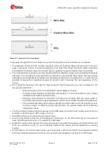
The module shall be placed in the center of an edge of the host PCB.
•
A large ground plane on the host PCB is a prerequisite for good antenna performance. It is
recommended to have the ground plane extending at least 10 mm on the three non-edge sides of
the module. See also Figure 22.
•
The host PCB shall include a full GND plane underneath the entire module, with a ground cut out
under the PCB trace antenna according to the description in Figure 23.
•
The NINA-W1x6 has four extra GND pads under the antenna that need to be connected for a good
antenna performance. Detailed measurements of the footprint including this extra GND pads can
be found in the NINA-W1 series data sheets [3] [4].
•
High / large parts including metal shall not be placed closer than 10 mm to the module’s antenna.
•
At least 10 mm clearance between the antenna and the casing is recommended. If the clearance
is less than 10 mm, the antenna performance can be adversely affected.
•
The module shall be placed such that the antenna faces outwards from the product and is not
obstructed by any external items in close vicinity of the products intended use case.
Figure 22: GND plane guard area enclosing the NINA-W1x6 module

