


LENA-R8 series - System integration manual
UBX-22015376 - R02
Design-in
Page 41 of 116
C1-Public
GND
Power path management IC
Vout
Vin
θ
Li-Ion/Li-Pol
Battery Pack
GND
System
12 V
Primary
Source
Charge
controller
DC/DC
converter and
battery FET
control logic
Vbat
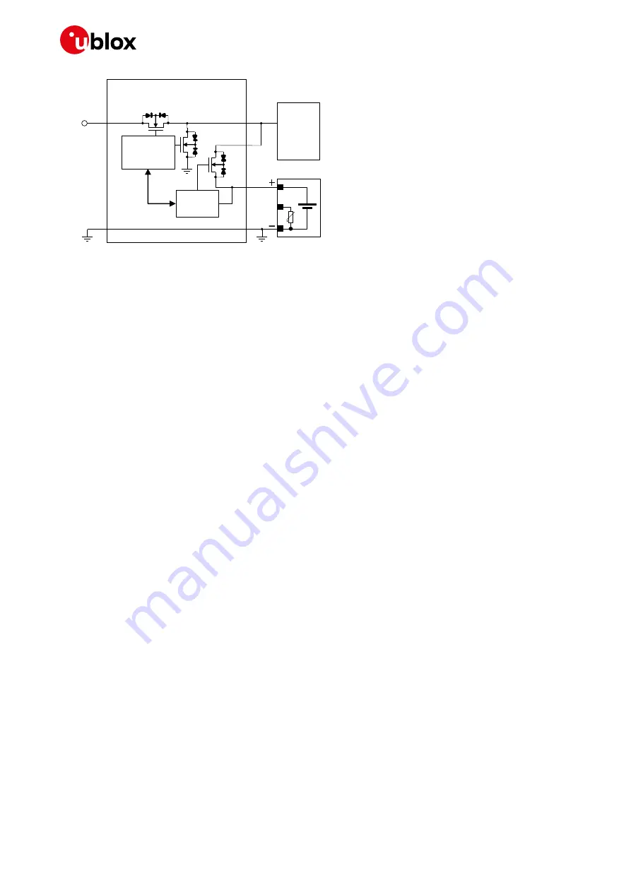
Figure 23: Charger / regulator with an integrated power path management circuit block diagram
provide an application circuit example where the MPS
MP2617H switching charger / regulator with an integrated power path management function
provides the supply to the cellular module, while concurrently and autonomously charging a suitable
Li-ion (or Li-Polymer) battery with the proper pulse and DC discharge current capabilities and the
proper DC series resistance according to the rechargeable battery recommendations described in
section
The MP2617H IC constantly monitors the battery voltage and selects whether to use the external
main primary supply / charging source or the battery as the supply source for the module, and starts
a charging phase accordingly.
The MP2617H IC normally provides a supply voltage to the module regulated from the external main
primary source allowing immediate system operation even under missing or deeply discharged
battery conditions: the integrated switching step-down regulator is capable of providing up to 3 A
output current with low output ripple and fixed 1.6 MHz switching frequency in PWM mode operation.
The module load is satisfied in priority, then the integrated switching charger will take the remaining
current to charge the battery.
Additionally, the power path control allows an internal connection from the battery to the module with
a low series internal ON resistance (40 m
typical), in order to supplement additional power to the
module when the current demand increases over the external main primary source or when this
external source is removed.
Battery charging is managed in three phases:
•
Pre-charge constant current
(active when the battery is deeply discharged): the battery is
charged with a low current, set to 10% of the fast-charge current
•
Fast-charge constant current
: the battery is charged with the maximum current, configured by
the value of an external resistor to a value suitable for the application
•
Constant voltage
: when the battery voltage reaches the regulated output voltage (4.2 V), the
current is progressively reduced until the charge termination is done. The charging process ends
when the charging current reaches the 10% of the fast-charge current or when the charging timer
reaches the value configured by an external capacitor.
Using a battery pack with an internal NTC resistor, the MP2617H IC can monitor the battery
temperature to protect the battery from operating under unsafe thermal conditions.
Several parameters, such as the charging current, the charging timings, the input current limit, the
input voltage limit, and the system output voltage, can be easily set according to the specific
application requirements, as the actual electrical characteristics of the battery and the external
supply / charging source: proper resistors or capacitors must be accordingly connected to the related
pins of the IC.


