background image

EVK-VERA-P174 - User Guide 

UBX-17048707 - R06 


Evaluation kit description 


Page 7 of 30 

1.5


Specifications 

Table  2  and  Table  3  list  the  absolute  maximum  ratings  and  operating  conditions  for  the  
EVK-VERA-P174: 

Symbol 

Description 

Min.  

Max. 

Unit 

V_Sys 

Main power supply 9 – 28 V 

-0.3 

28.0 

5V0_A1, 
5V0_A2 

Power supply voltage 5 V 

-0.3 

6.0 

3V3 

Power supply voltage 3.3 V 

-0.3 

3.9 

VIO 

I/O supply voltage 1.8 V/3.3 V 

-0.3 

3.9 

T

STORAGE


Storage temperature 

-40 

+95 

ºC 

Table 2: Absolute maximum ratings 

Symbol 

Description 

Min.  

Typ 

Max. 

Unit 

V_Sys 

Main power supply voltage 

12 

28 

5V0_A1, 
5V0_A2 

Power supply voltage 5.0 V 

4.5 

5.0 

5.5 

3V3 

Power supply voltage 3.3 V 

3.0 

3.3 

3.6 

VIO 

I/O supply voltage 1.8 V/3.3 V 

1.65 

1.8 

1.95 


3.0 

3.3 

3.6 

T

A


Ambient operating temperature 

- 40 

+ 95 

ºC 

Ripple Noise 

Peak-to-peak voltage ripple on 3V3 supply lines 

175 

mV 


Peak-to-peak voltage ripple on 5V0 supply lines. 


125 

mV 

Table 3: Operating conditions 

Symbol 

Description 

Conditions 

Typ 

Max. 

Unit 

V

IH


Input high voltage 


0.7*VIO

1


VIO

1


V

IL


Input low voltage 


-0.3 

0.6

2


V

HYS


Input hysteresis 


0.18 

V

OH


Output high voltage 

I

O

max = 5 mA 

VIO - 0.4 

V

OL


Output low voltage 

I

O

max = -5 mA 

0.4 

Table 4: Digital pad ratings 


1

 1PPS pad always uses 1.8 V internally generated IO supply regardless of the VIO pad voltage. 

2

 RSTn pad is internally pulled high to VIO voltage by 100k. During reset, it should be below 0.2 V. 


Summary of Contents for EVK-VERA-P174

Page 1: ...A P1 Host based V2X transceiver modules User Guide Abstract This document describes how to set up the EVK VERA P174 evaluation kit to evaluate the VERA P1 series host based 802 11p V2X transceiver mod...

Page 2: ...property rights in the products names logos and designs included in this document Copying reproduction modification or disclosure to third parties of this document or any part thereof is only permitt...

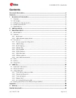
Page 3: ...figuration 12 3 3 2 USB interface 12 3 3 3 Bootstrapping 12 3 3 4 SPI interface 12 3 3 5 SPI chip select 13 3 3 6 1PPS interface 13 3 3 7 GNSS interface 13 3 3 8 SMA connectors 14 3 3 9 Host interface...

Page 4: ...EVK VERA P174 User Guide UBX 17048707 R06 Page 4 of 30 Revision history 29 Contact 30...

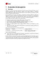
Page 5: ...ctors for the VERA P1 module Has an integrated u blox NEO M8U GNSS module with SMA antenna connector Has an on board SPI flash for evaluating different boot options Provides an integrated USB 2 0 hub...

Page 6: ...e Quick Start card 1 3 Software and documentation The Linux drivers firmware and basic evaluation tools for the VERA P1 series modules are available via u blox support Distribution of the software req...

Page 7: ...ly voltage 5 0 V 4 5 5 0 5 5 V 3V3 Power supply voltage 3 3 V 3 0 3 3 3 6 V VIO I O supply voltage 1 8 V 3 3 V 1 65 1 8 1 95 V 3 0 3 3 3 6 V TA Ambient operating temperature 40 95 C Ripple Noise Peak...

Page 8: ...Boot_1 to select the USB DFU boot mode 3 Connect two external 5 9 GHz antennas to the SMA antenna connectors of the VERA P1 series module Always make sure that the RF ports are properly terminated to...

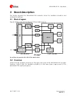
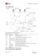
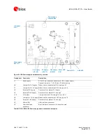
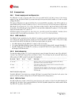
Page 9: ...gure 3 Block diagram of the EVK VERA P174 evaluation board 3 2 Overview Table 5 lists the available connectors on the upper main board of the EVK VERA P174 and their functions Table 6 lists the availa...

Page 10: ...eader to measure current on 5V rail J102 ANT1 SMA connector for antenna 1 of VERA P1 J103 ANT2 SMA connector for antenna 2 of VERA P1 J113 SPI CS Jumper to configure SPI chip select routing between VE...

Page 11: ...ternal 5 V supply Connector for external 5 V supply J4 External 3 3 V supply Connector for external 3 3 V supply J10 VIO select Jumper to select VIO voltage 1 8 V or 3 3 V J9 Jumper for 1 8 V supply D...

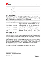
Page 12: ...interface of the VERA P1 module on the main board The u blox NEO M8U GNSS module on the main board via a USB to UART bridge FT234XD T The SPI interface of the VERA P1 module or on board SPI flash on...

Page 13: ...1 2 4 5 6 Used to connect VERA P1 to the SPI flash for firmware or bootloader download when boot mode SPI master is selected see 3 3 3 Host to VERA P1 via J105 3 2 4 4 5 6 Used to connect VERA P1 to t...

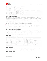
Page 14: ...kits include a minimum attenuation of 50 dB to avoid damage to the modules 3 3 9 Host interface connector The host interface connector is used in the EVK to connect the VERA P1 main board to the powe...

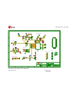
Page 15: ...age 15 of 30 The schematics for the EVK VERA P174 are shown in Figure 6 and Figure 7 Full design files are also available via u blox support To obtain these documents send an email to the support team...

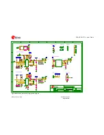
Page 16: ...EVK VERA P174 User Guide UBX 17048707 R06 Board description Page 16 of 30 Figure 6 Schematic of the VERA P1 main board page 1 2...

Page 17: ...EVK VERA P174 User Guide UBX 17048707 R06 Board description Page 17 of 30 Figure 7 Schematic of the VERA P1 main board page 2 2...

Page 18: ...EVK VERA P174 User Guide UBX 17048707 R06 Board description Page 18 of 30 Figure 8 Schematic of the power supply board page 1 2...

Page 19: ...EVK VERA P174 User Guide UBX 17048707 R06 Board description Page 19 of 30 Figure 9 Schematic of the power supply board page 2 2...

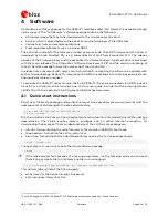
Page 20: ...via USB to a native Linux PC or a virtual machine running Linux For this user guide a virtual machine running Ubuntu 18 04 LTS with Linux kernel 4 15 0 23 generic x86_64 has been used 4 1 Quick start...

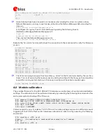
Page 21: ...ile images SDRMK5Dual bin sudo password for user dfu util 0 9 Copyright 2005 2009 Weston Schmidt Harald Welte and OpenMoko Inc Copyright 2010 2016 Tormod Volden and Stefan Schmidt This program is Free...

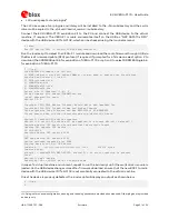
Page 22: ...t Source External 53 1024 Last Reset Source External 54 1024 The llc tool and plugins require the shared library libLLC so that it can be located by the run time linker This is set up during the make...

Page 23: ...lays details of the last transmitted frames by the PHY chconfig Sets the channel configuration for both radios test tx Generates and transmits test packets test rx Receives test packets Table 10 Descr...

Page 24: ...rings 0 2765 0 0 Rx Frame Firings 0 2765 0 0 4 3 2 Channel configuration Two different channel configurations are available per radio on the VERA P1 which can be configured by using the chconfig LLC p...

Page 25: ...st SeqNum 90 100 Packet rate Current 10 0 Target 10 0 Tx Last SeqNum 100 100 Packet rate Current 9 8 Target 10 0 4 3 4 Receiver test The test rx command is used to receive test packets sent by another...

Page 26: ...les must be configured to use the same DSRC channel The module option IPv6Enabled 1 must be provided when the driver module is loaded to enable IPv6 support The optional argument IPv6MCS can be used t...

Page 27: ...red kernel sources should be available in the home duser work linux 3 10 107 directory Recipes for integrating the software package into Yocto based projects can be provided by u blox on request To cr...

Page 28: ...tion Board EVK Evaluation Kit IEEE Institute of Electrical and Electronics Engineers ITS Intelligent Transport Systems GNSS Global Navigation Satellite System GPS Global Positioning System MAC Medium...

Page 29: ...u blox com Revision history Revision Date Name Comments R01 24 Aug 2017 mzes shoe kgom Initial release R02 20 Oct 2017 mzes kgom Removed references to VERA P175 R03 25 Apr 2018 shoe Fixed a typo in t...

Page 30: ...Office China Beijing Phone 86 10 68 133 545 E mail info_cn u blox com Support support_cn u blox com Regional Office China Chongqing Phone 86 23 6815 1588 E mail info_cn u blox com Support support_cn...

Reviews: