EVK-VERA-P174 - User Guide
UBX-17048707 - R06
Board description
Page 10 of 30
3.2.1
Main board
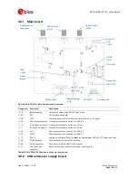
Figure 4: EVK-VERA-P1 Main board assembly overview
Designator Connector
Description
J112
Bootstrapping
Jumpers to select the VERA-P1 boot mode
J105
SPI
SPI interface connector
J108
1PPS
Jumper and connector for the internal or external 1PPS signal
J109
3V3 current measure Pin header to measure current on 3V3 rail
J110
VIO current measure Pin header to measure current on VIO rail
J111
5V current measure
Pin header to measure current on 5V rail
J102
ANT1
SMA connector for antenna 1 of VERA-P1
J103
ANT2
SMA connector for antenna 2 of VERA-P1
J113
SPI CS
Jumper to configure SPI chip select routing between VERA-P1, SPI flash, and host
J104
GNSS antenna
SMA connector for the GNSS antenna
J106
GNSS connector
Connector for GNSS UART/1PPS signals
J101
Host interface
connector
Board-to-board connector to the power supply board
Table 5: EVK-VERA-P174 Main board connector description
3.2.2
USB and power supply board
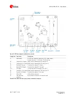
Bootstrapping
(J112)
1PPS
(J108)
Reset
button
VERA-P1 ANT 1
(J102)
VERA-P1 ANT 2
(J103)
GNSS antenna
connector
(J104)
GNSS (J106)
Reset LED
Firmware LED
1PPS LED
5V (J111)
3V3
(J109)
SPI CS
(J113)
SPI (J105)
VIO (J110)

