EVK-VERA-P174 - User Guide
UBX-17048707 - R06
Board description
Page 13 of 30
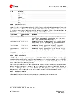
Pin No.
Assignment
1
SPI data MISO
2
VIO
3
SPI clock
4
SPI data MOSI
5
SPI chip select
6
GND
3.3.5
SPI chip select
The EVK-VERA-P174 contains an 8 Mbit SPI flash (SST25VF080B), which can be used to store the
radio firmware or a different bootloader for the VERA-P1 module. The SPI chip select pin header
(J113) on the main board is used to configure the routing of the SPI chip select signal between the
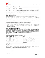
VERA-P1, host, and SPI flash. Table 8 shows the possible configurations:
SPI CS routing
Jumper settings
3
(J113)
Description
Host to flash via USB
2 (1-3)
Used to program the flash from the host over USB. The SPI flash is
accessible via the USB interface on the power supply board. A USB-to-SPI
bridge (FT2232H) connects the SPI flash to the USB.
Host to flash via J105
2 (1-3), 4 (5-6)
Used to program the flash from the host directly over SPI. The SPI flash is
accessible via the SPI interface connector or the host interface connector.
Jumper on 5-6 is used to disable the USB-to-SPI bridge.
VERA-P1 to flash
1 (1-2), 4 (5-6)
Used to connect VERA-P1 to the SPI flash for firmware or bootloader
download, when boot mode “SPI master” is selected (see 3.3.3).
Host to VERA-P1 via
J105
3 (2-4), 4 (5-6)
Used to connect VERA-P1 to the host over SPI, when boot mode “SPI slave”
is selected (see 3.3.3). The VERA-P1 SPI interface is accessible via the SPI
interface connector or the host interface connector.
Table 8: SPI Chip select configuration
3.3.6
1PPS interface
A 1PPS UTC reference signal is required by the IEEE1609.4 MAC inside the module to align
transmissions during channel switching and timekeeping. The 1PPS pin header J108 on the main
board can be used to connect the 1PPS signal from the on-board NEO-M8U GNSS receiver to the
1PPS signal input of the VERA-P1 module.
Place a jumper on pins 1 and 2 of the 1PPS pin header to connect the 1PPS signal from the NEO-M8U
GNSS module to the VERA-P1 module. The Pin 2 (VERA-P1 1PPS) and 3 (GND) can be used to
connect a 1PPS signal from an external GNSS to the VERA-P1 module. The signal level for the
external 1PPS can be in the range from 1.8 – 5 V and is converted to 1.8 V via a level shifter.
3.3.7
GNSS interface
The signals of the GNSS UART and 1PPS signal are available on the connector J106.
3
Italic number is the designation as printed on the EVK


