3
Figure 3. USB-to-AC Adapter.
Once powered, the CC1 will display a startup screen for five seconds on the unit’s blacklit LCD.
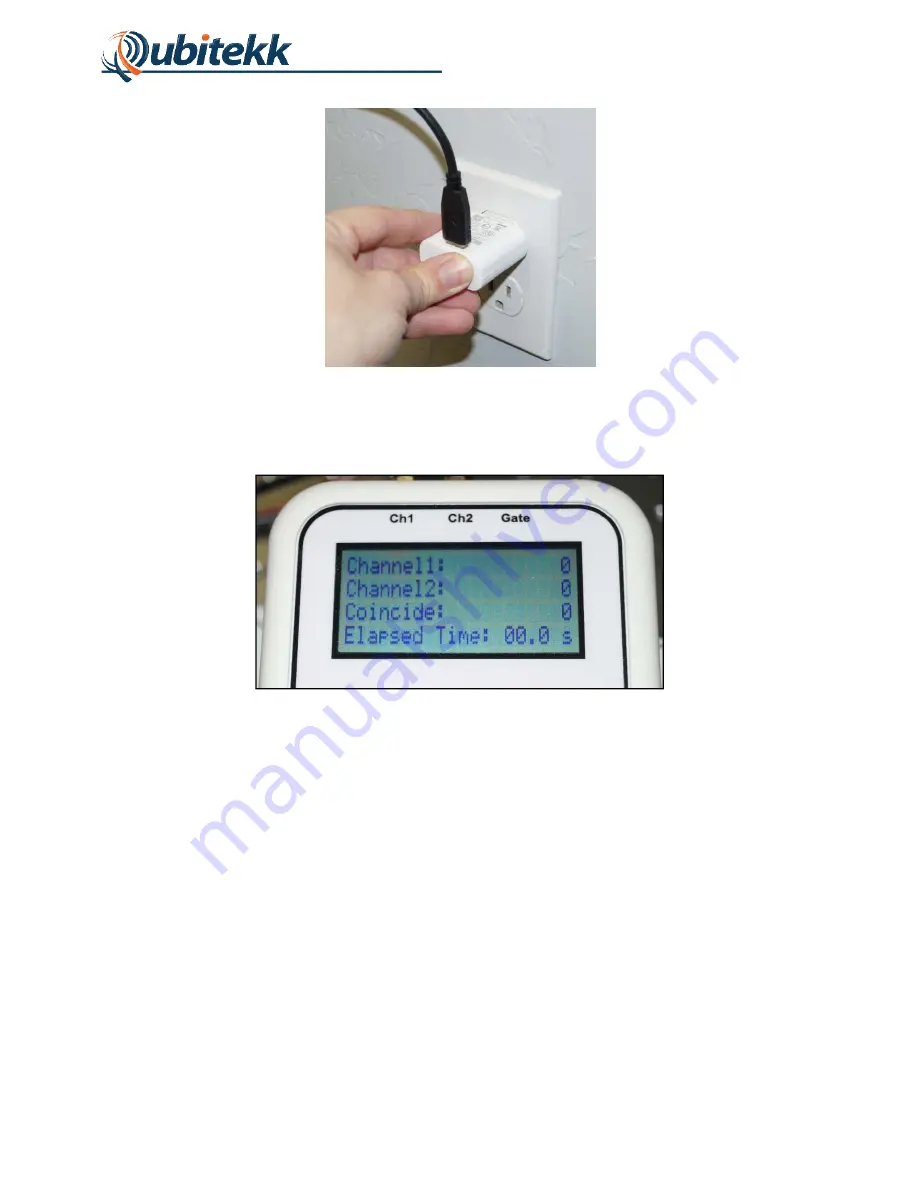
The unit’s “Count Screen” will then be displayed as shown in Figure 4.
Figure 4. Count Screen on startup.
To connect signals to the CC1, three SMA connector jacks are available at the top of the unit.
To detect coincident pulses, Channels 1 and 2 must both be connected to a pulse signal. If the
counting of single and coincidence pulses should be gated (see next section for more details),
then the third channel (“GATE”) should be connected to the associated gate pulse.
1.4
Navigating the Menus
The CC1 has six buttons on its front face. The buttons, along with signal connectors and
peripheral ports, are shown in Figure 4.
Summary of Contents for CC1
Page 1: ...CC1 Handheld Coincidence Counter USER S MANUAL Rev 1 02 June 1 2015 www qubitekk com...
Page 7: ...4 Figure 4 CC1 Buttons and Ports...
Page 23: ...20 APPENDIX A Electrical Schematics and Connections...
Page 24: ...21 A 1 Top Board LCD Display...
Page 25: ...22 A 2 Bottom Board FPGA and Microprocessor...
Page 26: ...23...
Page 27: ...24...


