background image

8. Repeat steps 4 and 5 until you achieve an optimal link, with all four Signal LEDs

solidly lit. This ensures the best possible data rate between the airFiber radios.

9. Lock the alignment on both airFiber antennas by tightening all the nuts and

bolts.

10. Observe the Signal LEDs of each airFiber radio to ensure that the values

remain constant while tightening the nuts and bolts. If any LED value changes
during the locking process, loosen the nuts and bolts, finalize the alignment of
each airFiber antenna again, and retighten the nuts and bolts.

Installer Compliance Responsibility

Devices must be professionally installed and it is the professional installer’s
responsibility to make sure the device is operated within local country regulatory
requirements.

Antenna

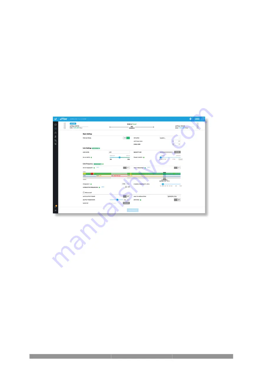
Select your antenna from the list. If Auto Output Power is enabled, transmit output
power is automatically adjusted to comply with the regulations of the applicable
country. For a Custom antenna, Antenna Gain is entered manually. Note the
requirements and antenna types listed below.

Cable Loss (When applicable)

Enter the cable loss in dB. Output power is adjusted to compensate for loss
between the radio and the antenna.

Certified Antenna Types

This radio transmitter FCC ID: SWX-AF5XHD / IC: 6545A-AF5XHD has been
approved by FCC / ISED Canada to operate with the antenna types listed below
with the maximum permissible gain for each antenna type indicated. Antenna
types not included in this list or having a gain greater than the maximum gain
indicated for that type, are strictly prohibited for use with this device.

Summary of Contents for airFiber AF-5XHD

Page 1: ...Vent and Gasket Gigabit PoE 24V 1A with Mounting Bracket Power Cord Package Contents Antenna Compatibility The airFiber AF 5XHD radio is designed for use with the following airFiber X antenna models...

Page 2: ...the top of the tower Ground wires min 10 AWG 5 mm and max length 1 m As a safety precaution ground the airFiber radio to grounded masts poles towers or grounding bars WARNING Failure to properly grou...

Page 3: ...r Antenna Connectors GPS Antenna Connector Signal LEDs Used to attach RF antenna cables not included Used to attach the GPS Antenna Signal 4 LED will light blue when on Signal 3 LED will light green w...

Page 4: ...Hz flash This continues until the AF 5XHD is fully booted Signal Level Once fully booted the Signal 1 4 LEDs act as a bar graph showing how close the AF 5XHD is to ideal aiming This is auto scaled bas...

Page 5: ...d Ethernet port for configuration In Band Management is enabled by default in the airFiber Configuration Interface When In Band Management is disabled the MGMT port is the only port that can monitor c...

Page 6: ...MT port Configure the AF 5XHD Recommended Install the IP67 Upgrade Kit included to prevent intrusion by water dust and insects Install a ground wire and mount the AF 5XHD on an airFiber X or RocketDis...

Page 7: ...y 4 airFiber Configuration The instructions in this section explain how to access the airFiber Configuration Interface and configure the following settings Wireless Mode Configure one AF 5XHD as the M...

Page 8: ...on your mobile device Note By default Bluetooth is enabled on the AF 5XHD 3 On the Connections screen select the AF 5XHD 4 Enter ubnt in the Username and Password fields Select your Country and Langua...

Page 9: ...for Master Mode b Enter a name in the Link Name field This should be the same on both the Master and the Slave c Select your Country d If needed change the Channel Bandwidth Frequency Output Power EIR...

Page 10: ...for the Data port a Tap Configuration and then tap Network b For both the Data LAN Network and Management Network options DHCP Have your router use DHCP reservation to assign a unique IP Address Stat...

Page 11: ...igure the Ethernet adapter on your computer with a static IP address on the 192 168 2 x subnet 3 Launch your web browser In the address field type the address of the port you are using to manage the d...

Page 12: ...k Save Changes 8 Configure each airFiber radio with a unique IP address for the Data port a Click the icon b For both the Data IP Address and Management IP Address options DHCP Have your router use DH...

Page 13: ...Note Do not damage or remove the post on the Port Cover 2 3...

Page 14: ...4 Hardware Installation Installing the Ground Wire 1...

Page 15: ...our airFiber radio will void your warranty Note The ground wire should be as short as possible and no longer than one meter in length Mount to an airFiber X Antenna Note To mount the AF 5XHD to a Rock...

Page 16: ...2 3...

Page 17: ...4...

Page 18: ...ing the AF 5XHD on a RocketDish equipped with the AF 5G OMT S45 Conversion Kit the Universal Bracket is not needed Refer instead to the Mount to an airFiber X Antenna section for instructions The Rock...

Page 19: ...Mount the External GPS Antenna Locate a mounting point that has a clear view to the sky and is above and as far away as possible from the AF 5XHD 1 OR 2 3...

Page 20: ...Connecting Power over Ethernet 1 2 OR...

Page 21: ...e the unit and void the product warranty Optional Surge Protection For added protection install two surge suppressors such as the Ubiquiti Ethernet Surge Protector model ETH SP at the end of each link...

Page 22: ...improper orientation of a mounting pole or significant elevation differences between airFiber radios Establishing a Link Adjust the positions of the Master and the Slave to establish a link The follo...

Page 23: ...1 Master Visually aim the Master at the Slave To adjust the Master s position adjust the azimuth and the elevation Adjust the azimuth 2 3...

Page 24: ...he Link LED is solidly lit green and the Signal LEDs of the Slave are displaying signal levels 6 Slave Aim the Slave at the Master to achieve the strongest signal level on the Master Note Refer to the...

Page 25: ...e the device is operated within local country regulatory requirements Antenna Select your antenna from the list If Auto Output Power is enabled transmit output power is automatically adjusted to compl...

Page 26: ...1 10 100 1000 Ethernet Port Management Port 1 10 100 1000 Ethernet Port Bluetooth v4 0 Mounting airFiber X Mount Rocket Mount Compatible GPS Pole Mount Included Operating Temperature 40 to 55 C 40 to...

Page 27: ...ted on the manufacturer s label Connection to a different power source than those specified may result in improper operation damage to the equipment or pose a fire hazard if the limitations are not fo...

Page 28: ...cepter tout brouillage radio lectrique subi m me si le brouillage est susceptible d en compromettre le fonctionnement This equipment has been tested and found to comply with the limits for a Class B d...

Page 29: ...of CISPR 32 In a residential environment this equipment may cause radio interference Brazil Nota Este equipamento n o tem direito prote o contra interfer ncia prejudicial e n o pode causar interfer nc...

Page 30: ...8 GHz frequency band is prohibited in BFWA member states Other countries listed may use the 5 8 GHz frequency band WEEE Compliance Statement Declaration of Conformity Online Resources 2020 Ubiquiti I...

Reviews: