27
Chapter 6: Network Tab
airFiber AF-11FX User Guide
Ubiquiti Networks, Inc.
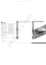
Ethernet Carrier Drop Settings
The
Ethernet Carrrier Drop
settings are used to control
failover switching between the primary and backup link in
response to capacity loss due to rain.
Carrier Drop Operation
This setting is used to control
the
Ethernet Carrier Drop
feature. Settings are:
Disabled
,
Enabled
, and
Use Pulse
. The default is
Disabled
.
Use Pulse
and
Enabled
are the two different methods used
to signal to the failover mechanism that it should switch to
the backup link:
•
Use Pulse
The LAN link is toggled off.
•
Enabled
The LAN link will be turned off and left off.
Pulse Duration
(Available if
Carrier Drop Operation
is set
to
Use Pulse
.) This is the length of time that the LAN link
remains down to trigger failover. The default is
5
seconds.
Block Data After Pulse
(Available if
Carrier Drop
Operation
is set to
Use Pulse
.) Enable this option to stop
data from passing through the link when it is experiencing
loss of capacity. The default is
Off
.
Enable Ethernet If No Session
Enable this option to
allow management data (such as GUI, SNMP, and ping
packets) to pass, even if the
Block Data After Pulse
option is
enabled. The default is
Off
.
Wait for First Session
Enable this option to cause the
system to wait until the Ethernet link has been successfully
established following a power cycle, to keep the link
from being dropped due to the throughput being below
threshold. The default is
Off
.
First Session Validation Timer
Use this setting to specify
how long to wait before triggering a link failure due to
insufficient threshold capacity following a power cycle.
The default is
0
seconds.
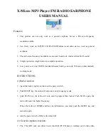
TX Capacity Low Threshold
This is the minimum
allowable TX capacity; if the TX capacity goes below this
threshold, the Ethernet link will be dropped. The default is
0
Mbps.
TX Capacity High Threshold
This is the TX capacity
required before a dropped link can be declared to be
operational again. The Ethernet link will remain down
until the TX capacity reaches this threshold. The default
is
0 Mbps. This setting should be greater than the TX
Capacity Low Threshold
to avoid flutter and multiple OSPF
convergences.
RX Capacity Low Threshold
This is the minimum
allowable RX capacity; if the RX capacity goes below this
threshold, the Ethernet link will be dropped. The default is
0
Mbps.
RX Capacity High Threshold
This is the RX capacity
required before a dropped link can be declared to be
operational again. The Ethernet link will remain down
until the RX capacity reaches this threshold. The default
is
0 Mbps. This setting should be greater than the RX
Capacity Low Threshold
to avoid flutter and multiple OSPF
convergences.
Low Threshold Timer
This is the number of continuous
seconds that the radio must remain under the minimum
TX or RX capacity threshold before the link is dropped. If
set to 0, then as soon as capacity drops below a set limit,
the Ethernet link will be dropped. Default is
0
seconds.
High Threshold Timer
This is the number of continuous
seconds that the radio must remain above the maximum
TX or RX capacity threshold before the link is declared
operational again. The default is
0
seconds.
Summary of Contents for airFiber 11FX
Page 1: ...11 GHz FDD Licensed Backhaul Radio Model AF 11FX...
Page 2: ......
Page 6: ...iv Table of Contents airFiber AF 11FX User Guide Ubiquiti Networks Inc...
Page 10: ...4 Chapter 1 Overview airFiber AF 11FX User Guide Ubiquiti Networks Inc...
Page 20: ...14 Chapter 2 Installation airFiber AF 11FX User Guide Ubiquiti Networks Inc...
Page 26: ...20 airFiber AF 11FX User Guide Ubiquiti Networks Inc...
Page 30: ...24 airFiber AF 11FX User Guide Ubiquiti Networks Inc...
Page 34: ...28 Chapter 6 Network Tab airFiber AF 11FX User Guide Ubiquiti Networks Inc...
Page 38: ...32 Chapter 7 Services Tab airFiber AF 11FX User Guide Ubiquiti Networks Inc...
Page 42: ...36 Chapter 8 System Tab airFiber AF 11FX User Guide Ubiquiti Networks Inc...
Page 50: ...44 Appendix K Safety Notices airFiber AF 11FX User Guide Ubiquiti Networks Inc...
Page 56: ...50 Appendix N Declaration of Conformity airFiber AF 11FX User Guide Ubiquiti Networks Inc...