UAB NAVITUS LT MCL 5 IP User Manual Download Page 10


10 

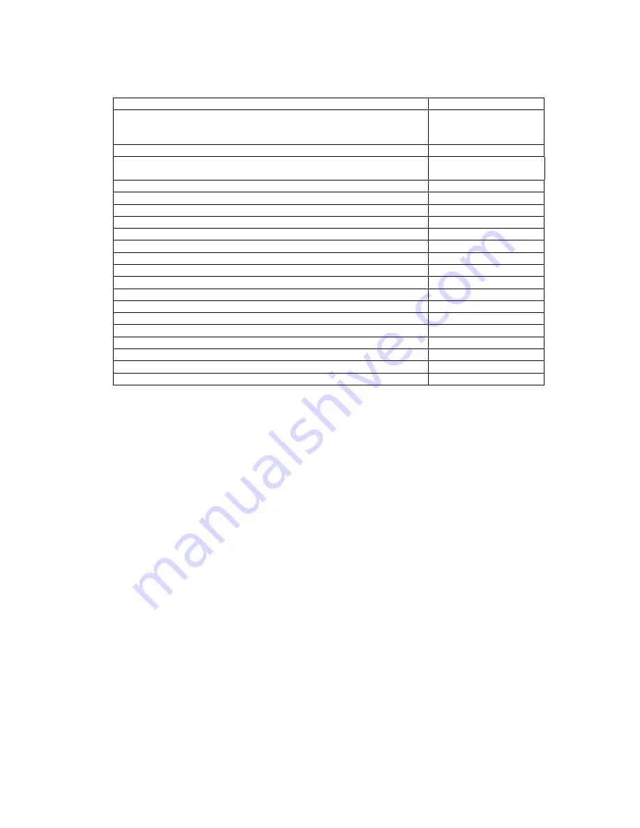
3.  Technical Characteristics  


Power supply input voltage range (50/60Hz) 

90 ... 264 V  

Power consumption: 

a.  maximum in transmission mode: 
b.  average in duty mode: 

 
< 10 VA 
< 5 VA 

Meter to controller net baud rate*, Baud 

300... 115200 

PC to controller net baud rate via USB device interface, 8N1 
bits, Baud 

115200  

Number of meters connected to RS485 interface 

1… 32 

Number of meters connected via optical Read-out Head 

Number of meters connected to RS232 interface  

Analogue input interface*, 12 bit, 0-48V 

Digital input interface, 100Hz* 

1  

Number of simultaneous communication sessions GSM/CSD/GPRS


6  

Internal thermometer measurement range*,


о

С 

- 4 0   . . .  +100** 

Work temperature range, 

о

С 

- 2 0   . . .  +60 

Storage temperature range, 

о

С 

- 4 0   . . .  +70 

Relative humidity, % without condensate 

20 ... 90 

Plastic Materials, safety of flammability 

ABS 

Internal Protection Marking 

IP-64 

Immunity to surge pulses from AC 230V 

6 kV (1,2/50 μs), 50 Ohm 

Dimensions, mm 

150x80x50 

RoHS  

Compliant 

Standards of electromagnetic interference and isolation 

Compliant 

IEC/TS 61000-6-5 certification* 

Compliant 

 * Depends on device modification  
 ** Elgama Sistemos Ltd guarantees that internal thermometer will be fully functioning in the range of the device 
work temperature as per above 

Table 3-1. MCL 5 IP controller technical characteristics 


Summary of Contents for MCL 5 IP

Page 1: ...Controller with internal Quad band GSM GPRS 3G modem MCL 5 IP User manual Version 2 0 UAB NAVITUS LT Lithuania 2018 ...

Page 2: ...G modem 1 0 Disclaimer UAB NAVITUS LT guarantees that the following documentation is correct and intended for the device described The manufacturer has no obligation for guarantee if the documentation is used for any other device not listed in this documentation UAB NAVITUS LT has the right to update or alter documentation without prior notice ...

Page 3: ...D OUT HEAD OVER RS485 14 4 4 CONNECTING A METER OR OPTICAL READ OUT HEAD OVER RS232 15 4 4 1 CONNECTING A METER OVER RS232 15 4 4 2 CONNECTING AN OPTICAL READ OUT HEAD OVER RS232 15 4 5 CONNECTING A PC OVER USB PORT FOR PARAMETERIZATION 15 5 LABELLING INFORMATION 16 6 PARAMETERIZATION GUIDE 16 6 1 INITIAL INFORMATION 16 6 2 PROCEDURE OF LOCAL PARAMETERIZATION 17 7 PARAMETERIZATION 21 7 1 SECURITY ...

Page 4: ... Provider IP Internet Protocol address IMEI International Mobile Equipment Identity LED Light Emitting Diode N A Not Available Not Applicable PC Personal Computer PIN Personal Identification Number Rx Receiver connector SIM Subscriber Identity Module SMA SubMiniature version A connector TCP IP Transmission Control Protocol Internet Protocol Tx Transmitter connector VPN Virtual Private Network URL ...

Page 5: ...the GSM GPRS controller MCL 5 IP National wiring rules should be followed while installing and using the controller All equipment interconnected with this product should comply with the requirements of EN 60950 1 2006 Personal computer etc or other adequate safety standard applicable to the equipment electricity meters GSM GPRS controller should be mounted in restricted access locations Only autho...

Page 6: ...abel BX TX X X Example B1 T1 1 1 Data Transfer Rates Baud 300 600 1200 2400 4800 9600 19200 0 300 600 1200 2400 4800 9600 19200 38400 115200 1 Internal Thermometer Not Present 0 Present 1 Digital Input Not Present 0 1 channel 1 Analogue Input Not Present 0 1 channel 1 Table 1 MCL 5 IP modification table ...

Page 7: ...devices 1 2 Supported Communication Protocols Controller supports two direction data exchange with communication protocols IEC 62056 31 DLMS COSEM all security layers as well or IEC 62056 21 1 3 Configuration RS232 and RS485 electric communication interfaces are used for meter data read out An Optical Read out Head can be connected to RS485 RS232 in order to read out meter data via the optical int...

Page 8: ... other input connection with indicated controller s Tx and controller s Rx connectors SIM card slot AC Power supply connector SMA female antenna socket GSM mode and signal strength indicators Power and USB indicators Meter activity indicators USB female socket for PC connection MCL 5 IP mounting holes ...

Page 9: ...ta Speed HSUPA cat 6 up to 5 76 Mb s UL HSDPA cat 8 up to 7 2 Mb s DL WCDMA PS up to 384 kb s DL UL EDGE multi slot class 12 up to 236 8 kb s DL UL Table 2 1 Main characteristics of a modem b Galvanically non separated communication interfaces USB device for local modem programming firmware update data reading and parameterization c Galvanically separated communication interfaces RS232 TX RX GND u...

Page 10: ... of simultaneous communication sessions GSM CSD GPRS 6 Internal thermometer measurement range оС 40 100 Work temperature range оС 20 60 Storage temperature range оС 40 70 Relative humidity without condensate 20 90 Plastic Materials safety of flammability ABS Internal Protection Marking IP 64 Immunity to surge pulses from AC 230V 6 kV 1 2 50 μs 50 Ohm Dimensions mm 150x80x50 RoHS Compliant Standard...

Page 11: ...ing CSD Registered to CSD network CONNECT GPRS CSD data session active connection established GSM Signal level range indication LED top Indicates signal strength 113 to 82 dBm or less LED middle Indicates signal strength 81 to 70 dBm LED bottom Indicates signal strength 69 to 51 dBm or more Default values indicated Signal indication level can be changed in the Menu Table 3 2 MCL 5IP controller ind...

Page 12: ...indicated below at the corners of the device Position the device vertically so that the face of the device is clearly visible for led indication and connection interfaces are easily accessible c Place the controller in the desired location and screw in the mounting bolts through the mounting holes d Insert the SIM card firmly into the dedicated slot e Gently place the SIM card in a slot marked SIM...

Page 13: ...her wire to the L phase socket 4 2 Sockets and Interfaces Controller sockets are shown in a table below INTERFACE CONNECTORS DESIGNATION RS485 B A Used for connecting up to 32 meters Optical Read out Head 5V B TX A RX GND Used for connecting an Optical Read out head Optical Read Out head is connected by using the same RS485 or RS232 connectors that are used for connecting a meter RS232 TX RX GND U...

Page 14: ... recommended to use UAB NAVITUS LT Optical Read out Head OKK or other manufacturers product compatible with the IEC 62056 21 standard The Optical Read out Head has four connection wires in total where its two wires should be connected to the same RS485 interface and remaining two wires to the controller s 5V 5 Volts and GND ground connectors found nearby according to the optical read out head spec...

Page 15: ...standard UAB NAVITUS LT OKK Optical Read out Head OKK for RS232 is connected in the following way Controller s Rx connector goes to OKK Tx connector and controller s Tx connector goes to OKK Rx connector Other manufacturers might have a different setup 4 5 Connecting a PC over USB Port For Parameterization Important Controller s USB connection can be used only after transparent cover is taken off ...

Page 16: ...st turned on wait about 30 seconds before connecting Important Parameterization may vary depending on connection interface type device version administrator s PC operating system region and version Therefore figures and menus given below may differ from actual due to software updates and upgrades Important It is required to disable PIN request on a SIM card before inserting it in the controller s ...

Page 17: ...ort for parameterization are independent from the settings for the data readout and can be set as follows 115200 bps parity none 8 data bits and flow control none After parameterization user must restart the controller s using the reset function in the menu Important To load or re load controller s menu press button ESC on keyboard 3 times Enter a name for the new connection Figure 6 2 1 Figure 6 ...

Page 18: ...18 Figure 6 2 3 Select port settings Figure 6 2 4 To change the values 1 Press Disconnect button as shown on figure 6 2 5 arrow 1 2 Press Properties button as shown on figure 6 2 5 arrow 2 ...

Page 19: ...19 Figure 6 2 5 3 Press Configure button as shown on figure 6 2 6 arrow 3 4 Press OK button as shown on figure 6 2 6 arrow 4 Figure 6 2 6 115200 ...

Page 20: ...ttings of the connection are set as shown on figures 6 2 7 Figure 6 2 7 The settings should change to 115200 8 N 1 as shown on figure 6 2 8 Figure 6 2 8 Important To load or re load controller s menu press button ESC on keyboard 3 times ...

Page 21: ...start when idle without having an engineer to interfere 7 5 Firmware update The firmware can be set to be updated automatically or manually 7 5 1 Automatic Firmware Update If set to automatic after restart controller will attempt automatic firmware download and update from the IP IP of a FTP server address indicated in the APN setting for a specific APN used 7 5 2 Manual Firmware update Depending ...

Page 22: ...pdate information High number of malformed or unexpected messages and errors Power supply recovery events Unauthenticated communication All events logs can be enabled disabled if required If event log is disabled event alert is disabled as well ...

Page 23: ...wledgment reception of alarm message 5 Plug Play server address Plug Play function alarm url address 6 Plug Play message send retry Times to retry sending the plug play message 7 Plug Play message send timeout Message timeout 3 Menu language of Public Menu language 4 Menu language of User Menu language 5 Menu language of Admin Menu language 6 Menu language of SuperAdmin Menu language 7 Device rebo...

Page 24: ...he main menu 1 Request to proceed timeout During the specified time the received request has to be send to a meter through RS485 RS232 out if it times out the request will be discarded 2 Data rate RS232 IN baud rate configuration 3 Data bits Define data bit quantity 4 Stop bits Define stop bit 5 Parity Define parity 6 Byte wait timeout Timeout value defined in byte transfer time it depends on baud...

Page 25: ...rk ID 5 2 Provider Name GSM Provider Network name 6 2 Provider FTP configuration 7 0 Return 8 1 FTP server URL FTP server address 9 2 FTP username FTP login username for firmware download 10 3 FTP password FTP login password for firmware download 11 3 Provider GPRS configuration 12 0 Return 13 1 User name GPRS network username 14 2 Password GPRS network password 15 3 APN Access point name 16 4 TCP...

Page 26: ...us 7 6 Modem GPRS status Modem GPRS status 8 7 Network mode Network mode 9 8 SIM Status Status of the SIM card 9 Battery voltage Battery voltage 10 Battery charging Battery charging 11 Start battery test Start battery test 12 Battery test status Battery test status 10 13 Read log Read log ...

Page 27: ...s server http downloads elgsis com files mcl5ip PF257938 zip zip or from the manufacturer s website http www st com web en catalog tools PF257938 Run the installation setup for 32 bits or 64 bits Windows platform and follow steps as shown below 1 Select proper windows platform and run the setum When the driver installation is completed plug the USB cable and go to system properties device manager ...

Page 28: ...28 2 Select STM32 cable and press Update Driver Software ...

Page 29: ...29 3 Press Browse my computer 4 Press Let me pick from a list 5 Select type Ports and press NEXT ...

Page 30: ...30 6 Select STMicroelectronics and press NEXT 7 Press YES 8 Installation completed ...

Page 31: ...31 9 Find port with name STMicroelectronics this is your USB cable port Remmember COM identification number ...

Page 32: ...nce on the electricity meter s data MCL 5 IP system will restart automatically and will start operating as normal as soon as the voltage is restored Guarantee period of the controller is 24 months The manufacturer has no obligation to service under the guarantee and provide free service in the following cases If communication lines were cut off or were shortened if they were connected to telephone...

Reviews: