background image

106636-02 - 12/19

21

 X-2

Installation, Operating & Service Manual

System Start-up and Checkout 

(continued)

CAUTION


Avoid operating boiler in an environment where 

saw dust, loose insulation fibers, dry wall dust, 

etc. are present.  If boiler is operated under 

these conditions, burner interior and ports 

must be cleaned and inspected daily to ensure 

proper operation.

!

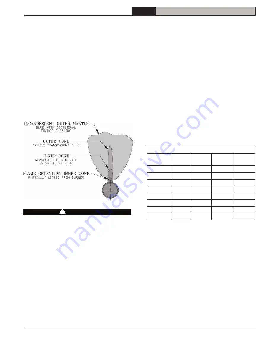
J.  Check Main Burner Flame (see Figure 9-6)
 

1. NORMAL FLAME:


a. Clearly defined inner cone with no yellow  

           tipping.


b. Orange-yellow streaks caused by dust  


    should not be confused with true yellow  


    tipping.


2.    ABNORMAL FLAME (if found, check inlet and  


outlet gas pressure. Procedure found in   


following steps):


a. Over fired - large flame


b. Under fired - small flames


c. Lack of primary air - yellow tipping on  

           flames.

K.  Check gas inlet pressure
 

1.  While boiler and all other gas appliances  


are not firing, gas inlet pressure should not  


exceed ½ psig.


2. While boiler and all other gas appliances   

    are firing, gas inlet pressure must be  


    between minimum and maximum shown    

    on rating label.

L.  Check gas outlet (manifold) pressure
 

1.   Install manometer on 1/8" outlet pressure  


tap on gas valve (see Figure 9-3). Use    


of shutoff valve between manometer and gas  


valve can prevent pressure surge that blows  


out manometer fluid.


2. Adjust regulator on gas valve so manifold  

    pressure matches values listed on rating label.


3. Turning regulator adjustment screw  


    clockwise (

) increases pressure.


4. Turning regulator adjustment screw  


     counterclockwise (

) decreases pressure.

M.  Check gas input rate to boiler
 

1.  When checking rate, ensure all other    


appliances connected to same meter as  


boiler are off.


2.  Input ratings shown on boiler rating label  


can be used for elevations up to 2,000 ft. For  


elevations 2,000 ft. or higher, reduce input  


rate to 4 percent per 1,000 ft. above sea level.  


Do not install at elevations above 12,000 ft.  


See Table below.

Figure 9-6:  Main Burner Flame

N.  Measure carbon monoxide (CO) level in vent after 

5 minutes of main burner operation. CO should 

not exceed 400ppm air free.

O.  Check vent damper operation.  
 

Vent damper must be in open position when 

appliance main burners are operating. 

Input (MBH)

Boiler 

Model

Rating 

Label

5,000 ft. 7,000 ft.

10,000 

ft.

X-202

38

30.5

27.5

23

X-203

70

56

50

42

X-204

105

84

76

63

X-205

140

112

101

84

X-206

175

140

126

105

X-207

210

168

151

126

X-208

245

196

176

147

X-209

280

224

202

168

Summary of Contents for X-2 X-202

Page 1: ...Service and Maintenance 28 How It Works 32 Troubleshooting 34 Service Parts 39 Appendix 46 TO THE INSTALLER Affix these instructions adjacent to boiler Provide model number and serial number when see...

Page 2: ...rate injury WARNING Indicates a hazardous situation that if not avoided could result in death or serious injury DANGER Explosion Hazard DO NOT store or use gasoline or other flammable vapors or liquid...

Page 3: ...ctrical Requirements 120VAC 60 Hz 1 ph Less than 12A Maximum Allowable Working Pressure 50 psi Boiler shipped from factory with a 30 psi safety relief valve 1 Input ratings can be used for elevations...

Page 4: ...ctor manufacturer s recommended clearances Additional height required to maintain 6 clearance from all breeching components Vent damper may be installed in vertical or horizontal section of vent conne...

Page 5: ...mums shown in Figures 1 3 and 1 4 F Install on level floor For basement installation provide concrete base if floor is not level or if water may be encountered on floor around boiler WARNING ASSURE TH...

Page 6: ...mo stat so appliance will operate continuously 5 Test for spillage at the draft hood relief opening after 5 minutes of main burner operation Use the flame of a match or candle or smoke from a cigarett...

Page 7: ...amper position indicating means to be visible following installation 4 Plug factory harness vent damper connector into damper motor polarized receptacle WARNING Do not alter draft hood or place any ob...

Page 8: ...evice Exception National Fuel Gas Code ANSI Z223 1 NFPA 54 and allow vent downsizing when vent size determined by their Vent Sizing Tables is smaller than draft hood outlet vent damper These codes req...

Page 9: ...located at least 8 ft from vertical wall or similar obstruction termination shall extend above roof in accordance with Figure 5 3 3 For terminations located less than 8 ft from vertical wall or simil...

Page 10: ...n 1 Safety relief valve and boiler 2 Safety relief valve and discharge Union may be installed in safety relief valve piping D Connect system supply and return piping to boiler Refer to Figures 6 1 6 2...

Page 11: ...m System Circulator System Zone Valves Zone Circulators Full Port Isolation Valves Flow Check From System Full Port Isolation Valves Drain Valve Safety Relief Valve Pipe within 6 of floor or drain Dra...

Page 12: ...in 6 of floor or drain Drain Valve IWH Return IWH Supply Indirect Water Heater IWH Air Separator Air Vent Expansion Tank Backflow Preventer Fill Valve Cold Water Return Full Port Isolation Valves Unio...

Page 13: ...s valve to gas supply system 1 Use methods and materials in accordance with local plumbing codes and requirements of gas supplier In absence of such requirements follow National Fuel Gas Code ANSI Z22...

Page 14: ...t must be run from main electrical service with an over current device disconnect in circuit A service switch is recommended and may be required by some local jurisdictions Connect to black and white...

Page 15: ...106636 02 12 19 15 X 2 Installation Operating Service Manual Figure 8 1 Wiring Connection Diagram 8 Electrical continued...

Page 16: ...106636 02 12 19 16 X 2 Installation Operating Service Manual Figure 8 2 Schematic Ladder Diagram 8 Electrical continued...

Page 17: ...106636 02 12 19 17 X 2 Installation Operating Service Manual 8 Electrical continued Figure 8 3 Wiring Schematic Zone Valves Figure 8 4 Wiring Schematic Zone Circulators...

Page 18: ...Figure 6 2 and 6 3 Note Terminate hose in five gallon bucket at a suitable floor drain or outdoor area 5 Starting with one circuit open zone valve or start circulator 6 Open drain valve 7 Open fill v...

Page 19: ...106636 02 12 19 19 X 2 Installation Operating Service Manual Figure 9 2 Operating Instructions 9 System Start up and Checkout continued...

Page 20: ...TAT to lowest setting 3 If limits are functioning properly LWCO Auxiliary limit flame rollout switch blocked vent switch damper boiler should spark If boiler does not spark see Section 14 Troubleshoot...

Page 21: ...ometer on 1 8 outlet pressure tap on gas valve see Figure 9 3 Use of shutoff valve between manometer and gas valve can prevent pressure surge that blows out manometer fluid 2 Adjust regulator on gas v...

Page 22: ...water condition Amber LOW WATER LED will illuminate and burner will shut down Release TEST button and burner will light off R Check high limit control See Section 10 Operation High Limit for details...

Page 23: ...to light off again Limit Open 15 There is a call for heat from thermostat but Limit is open Flame Present Out of Sequence 16 Flame signal is still present when expected to be 0 no flame Damper Failed...

Page 24: ...High Limit Differential Setpoint tt Heat Request Status dh DHW Heat Request Status FLA Flame Current run Run Time Hours CYC Boiler Cycles Err Error Press I key on control to change from one parameter...

Page 25: ...boiler water temperature is less than 140 F This feature helps save energy by satisfying home heating needs with residual boiler heat rather than cycling boiler 5 Start Temperature Amount of heat avai...

Page 26: ...Water Demand dh IWH limit is wired to DHW terminal on control DHW circulator is wired to DHW Circulator on control wire harness Table 6 shows circulator status with different combinations of TT Input...

Page 27: ...pressure Checked gas manifold pressure Checked CO level in vent Checked vent damper operation Check ignition system safety shut off device Tested LWCO functionality Tested high limit operation Tested...

Page 28: ...loose fitting clothing that is sufficiently tight around potential entry points for RCF dust 3 Gloves 4 Eye protection such as goggles safety glasses with side shields or full facepiece Take steps to...

Page 29: ...is in good condition and there are no openings into chimney 3 Remove soot accumulations with wire brush and vacuum 4 Repair or replace deteriorated vent pipe and vent accessories 5 Inspect piping to...

Page 30: ...Boiler Control 8 Install Burner Access Panel Connect Flame Rollout Switch wires E Inspect Water Piping 1 Check all system piping for leaks 2 Repair any leaks before placing back into service F Inspect...

Page 31: ...and Checkout Check LWCO Functionality S Check High Limit Control See Start up and Checkout Check High Limit Control T Check Thermostat Operation See Start up and Checkout Check Thermostat Operation U...

Page 32: ...and deactivates circulator Control module indicates boiler status and returns error codes if applicable See Troubleshooting for guidance with error codes 2 Transformer Control transformer reduces lin...

Page 33: ...r of Boiler 3 A B 4 4 3 3 UNLESS OTHERWISE NOTE ALL DIMENSIONS IN INCH TOLERANCES X X 1 X XXX 005 X XX 03 ANGLE 1 PROPER U S Boiler Co LANCAST THIS DOCUMENT CONTAINS CO AND ITS CONTENTS ARE THE SO COM...

Page 34: ...rious and potentially dangerous condition In the event the IDL 1200 detects a low water condition the system must be inspected by a qualified service technician before the boiler is returned to servic...

Page 35: ...n If 24Vac is present unplug vent damper harness from control With wire harness unplugged check for 24Vac between P6 5 on Control and ground If voltage present replace control If voltage not present f...

Page 36: ...r draft Always follow recommended clearances combustion air requirements and venting requirements Check Flame Rollout Switch in event of excessive blockage of boiler section flue passageways is develo...

Page 37: ...r recommended corrective action Flame sensed during pre purge before gas valve signaled open Check gas valve for proper operation Replace gas valve if problem persists Hard Lockout When a hard lockout...

Page 38: ...supply tubes of air b If no gas flow check following 24 volts across PV and MV PV at gas valve If voltage ok replace defective gas valve Check for break in wiring harness to gas valve 24 volts across...

Page 39: ...9617 03 1 109617 04 1 109617 05 1 109617 06 1 109617 07 1 109617 08 1 109617 09 1 Not Shown Blocked Vent Switch see Figure 5 1 109742 01 1 All X 2 Series Repair Parts may be obtained through your loca...

Page 40: ...07 1 109613 08 1 109613 09 1 2B Base Tray 2C Burner Tray 2D Base Side Insulation 2E Base Rear Insulation 2F Base Front Insulation 2G Drip Shields 2H Manifold Support Bracket 2J Base Front Panel 2K Fl...

Page 41: ...1 05 1 109731 06 1 N A Gas Manifold N A 109731 07 1 109731 08 1 109731 09 1 3C Burner Orifices Natural Gas 47 109733 01 1 16 orifices Burner Orifices LP Gas 1 20mm 109734 01 1 16 orifices 3D Pilot Bur...

Page 42: ...y No Description Part Number Quantity X 202 X 203 X 204 X 205 X 206 X 207 X 208 X 209 4A Control 103966 02 1 4B Transformer 106034 01 1 4C Temperature Sensor LWCO 106495 02 1 Not Shown Temperature Sen...

Page 43: ...acket Wrap around Jacket Panel 106357 03 1 106357 04 1 106357 05 1 106357 06 1 106357 07 1 106357 08 1 106357 09 1 5B Jacket Vestibule Panel 110126 02 1 110126 03 1 110126 04 1 110126 05 1 110126 06 1...

Page 44: ...209 6A Supply Water Manifold 109614 01 1 6B Temperature Pressure Gauge 105894 01 1 6C 30 PSI Relief Valve 109038 01 1 6D Drain Valve Obtain Locally 3 4 NPT boiler connection 6E Vent Damper 109634 01 1...

Page 45: ...ity X 202 X 203 X 204 X 205 X 206 X 207 X 208 X 209 7A Power Supply Harness 109639 01 1 7B Main Control Harness 109640 01 1 7A 7B Key No Description Part Number Quantity X 202 X 203 X 204 X 205 X 206...

Page 46: ...ide Appendix Combination Refrigeration Heating System Water Chiller Shut off valves Shut off valves Expansion Tank Circulator Supply main to combined heating cooling system Return main from combined h...

Page 47: ...ondensing during these heating season shoulders is unlikely to cause problems Larger volume systems during the shoulder heating seasons or systems with aggressive set back or low temperature systems w...

Page 48: ...A strap on temperature sensor measures boiler inlet temperatures This temperature signal is sent to a variable speed pump that will ensure boiler inlet temperatures are always greater than the factor...

Page 49: ...__________________________________________________ __________________________________________________________________________________________________ __________________________________________________...

Page 50: ...__________________________________________________ __________________________________________________________________________________________________ __________________________________________________...

Page 51: ...__________________________________________________ __________________________________________________________________________________________________ __________________________________________________...

Page 52: ...106636 02 12 19 52 X 2 Installation Operating Service Manual U S Boiler Company Inc P O Box 3020 Lancaster PA 17604 1 888 432 8887 www usboiler net...

Reviews: