background image

35

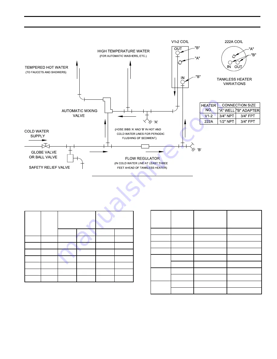
Figure 17A:  Schematic Tankless Heater Piping

TABLE 2A: TANKLESS HEATER DATA: 


Rear Mounted Heater on Steam and Water Boilers

TABLE 2B: TANKLESS HEATER DATA:  

Front Mounted Heater on Water Boilers

Boiler

Model

Heater 

No.

Heater Rating

(GPM)

Pressure Drop 

thru Heater

(PSI)

Steam  Water

Steam

Water

V8H3

V1-2

2.75

3

3.9

4.7

V8H4

V1-2

3

3.25

4.7

5.6

V8H5

V1-2

3.25

3.5

5.6

6.4

V8H6

V1-2

3.75

3.75

7.2

7.2

V8H7

V1-2

3.75

4

7.2

8

V8H8

V1-2

4

4.5

8

9.8

V8H9

V1-2

4

4.5

8

9.8

Boiler

Model

Heater 

No.

Heater Rating

(GPM)

Pressure Drop 

thru Heater

(PSI)

V8H3

222A

3

22

V8H4

222A

3.5

22

V8H5

222A

4

30.5

V8H6

222A

4.5

33

V8H7

222A

4.6

33

A54

5.5

36

V8H8

222A

4.75

40

A54

6

39.5

V8H9

222A

4.75

40

A54

6

39.5

SECTION  VII:  TANKLESS  AND  INDIRECT  WATER  HEATER  PIPING (cont'd)

Summary of Contents for V8H SERIES

Page 1: ...e l i o b o t s r i a p e r r o e c i v r e s r o F g n i t a R n o n w o h s s a r e b m u N l a i r e S d n a r e b m u N l e d o M r e l i o B e d i v o r p r e l i o b n o n o i t a m r o f n i r e l i o b e h t f o p o t n o d e t a c o l l e b a L r e b m u N l e d o M r e l i o B r e b m u N l a i r e S r e l i o B e t a D n o i t a l l a t s n I H 8 V r o t c a r t n o C g n i t a e H r e ...

Page 2: ...ccordance with National State and Local Plumbing Heating and Electrical Codes and the regulations of the serving utilities These Codes and Regulations may differ from this instruction manual Authorities having jurisdiction should be consulted before installations are made In all cases reference should be made to the following Standards CANADIAN BOILERS A Current Edition of Canadian Standards Assoc...

Page 3: ...to see that all controls are correctly installed and are operating properly when installation is complete including verifying that the limit sensor is fully installed seated in bottom of Well Failure to properly install Limit Sensor may result in property damage personal injury or loss of life due to elevated operating temperatures and or pressures This boiler is suitable for installation on combu...

Page 4: ...f this manual for details This boiler must be properly vented and connected to an approved vent system in good condition Do not operate boiler with the absence of an approved vent system This boiler needs fresh air for safe operation and must be installed so there are provisions for adequate combustion and ventilation air A clean and unobstructed chimney flue is necessary to allow noxious fumes th...

Page 5: ... 329 275 239 82 0 8 8 x 12 15 V8H9S 2 60 364 298 224 933 82 3 9 8 x 12 15 V8H9W 2 60 364 299 260 82 3 9 8 x 12 15 Boiler Model Suffix S Steam W Water SECTION I PRODUCT DESCRIPTION SPECIFICATION AND DIMENSIONAL DATA The V8H Series boiler is a cast iron oil fired water boiler designed for closed forced circulation heating systems or a low pressure steam boiler designed for use in closed heating stea...

Page 6: ...6 Figure 1A V8H3 thru V8H9 Water Boiler without Tankless Heater SECTION I PRODUCT DESCRIPTION SPECIFICATION AND DIMENSIONAL DATA continued ...

Page 7: ...7 Figure 1B V8H3 thru V8H9 Water Boiler with Front Tankless Heater SECTION I PRODUCT DESCRIPTION SPECIFICATION AND DIMENSIONAL DATA continued ...

Page 8: ...8 Figure 1C V8H3 thru V8H9 Water Boiler with Rear Tankless Heater SECTION I PRODUCT DESCRIPTION SPECIFICATION AND DIMENSIONAL DATA continued ...

Page 9: ...9 Figure 1D V8H3 thru V8H9 Steam Boiler with or without Tankless Heater SECTION I PRODUCT DESCRIPTION SPECIFICATION AND DIMENSIONAL DATA continued ...

Page 10: ...d boiler 4 PROVIDE SERVICE CLEARANCE of at least 24 clearance from front jacket panel for servicing and removal of front tankless heater increase to 30 for A54 heater If boiler is equipped with a rear tankless heater provide at least 24 service clearance on the right side of the boiler Boiler flueways may be cleaned either from the top or from the right side Provide at least 24 clearance from eith...

Page 11: ...ails or b Outdoor air may be provided with the use of two permanent openings which communicate directly or by duct with the outdoors or spaces crawl or attic freely communicating with the outdoors Locate one opening within 12 inches of top of space Locate remaining opening within 12 inches of bottom of space Minimum dimension of air opening is 3 inches Size each opening per following i Direct comm...

Page 12: ...BOILER Remove gauge valve and plugs from those tappings to be used Leave other tappings plugged or bushed according to Figure 5 E INSPECT JOINTS BETWEEN SECTIONS All joints are factory sealed If there are any spaces due to shipment or handling seal them with boiler putty F INSPECT FLUE COVER PLATES for tightness If loose retighten mounting hardware If flue plate or sealing rope is damaged repair o...

Page 13: ...A L4006A Operating Control N A N A L7224 Boiler Control G 1 Bushed to for Drain Valve Optional Return Return H 1 Return Plugged J 1 Surface Blowoff Plugged Flush Plug K 2 Front Supply 3 thru 9 Section Front Supply 3 thru 9 Section L 2 Plugged Optional Second Supply 3 thru 5 Section Required Second Supply 6 thru 9 Section Plugged 3 thru 9 Section M Safety Valve Relief Valve P Auxiliary Tapping Plug...

Page 14: ...two 2 5 16 18 x long cap screws securing the hinge bracket to the boiler section 2 Install jacket rear panel support bracket See Figure 6 Item 2A Align bracket with two 2 5 16 18 tapped holes in rear section and secure with two 2 5 16 18 x 1 2 long cap screws 3 Install jacket rear panel See Figure 6 Item 2B Align holes in jacket rear panel and support bracket Secure with two 2 8 x 1 2 long sheet m...

Page 15: ...n Paragraph I No 1 Check the burner swing door insulation and rope gasket for damage and adhesion If damaged replace insulation or gasket If insulation or gasket is loose reattach to swing door with RTV 732 or 736 silicone caulk 3 Install burner swing door in reverse order from Paragraph I No 1 4 Use the following procedure to properly close and secure the burner swing door after it has been remov...

Page 16: ...per electrode setting Readjust electrode setting to the proper dimensions if necessary g Reinstall Beckett MD V1 or MB L1 Head h Reinstall nozzle line electrode assembly i Connect copper connector tube j Inspect Beckett head setting on left side of burner by insuring the blue line MD V1 or the line on the label MB L1 are aligned readjust if necessary k Tighten knurled nut l Swing igniter closed ro...

Page 17: ...positioning bar matches the input oil nozzle installed in the burner refer to Table 12 at the rear of this manual In the case of the EZ 1HP the proper head positioning bar is still matched by the size of the nozzle not the input For example if nozzle size is 0 75 GPH input 150 psi is approximately 0 90 GPH and the proper bar is 0 75 GPH ii Model EZ 1HP Positioning Bars 0 50 GPH 0 60 0 65 GPH 0 75 ...

Page 18: ...adjusting crew clockwise to move the combustion head forward increasing the A dimension counterclockwise will pull the head back decreasing the A dimension To lock in place first tighten the thumb nut and then the locking screw c Initial Air Shutter Band Setting i The air shutter has a pointer which indicated the percent of opening against a calibrated scale 9 90 fully open 100 The setting is lock...

Page 19: ...index marker 3 is aligned with the correct index number in the Burner Setup Chart Table 12 at the rear of this manual iii Retighten the retaining nut 1 MODEL F5 3 thru 5 Section Zero and four are scale indicators only From left to right the first line is 4 and the last line 0 MODEL F10 6 thru 9 Section Same as above except scale indicators are 0 and 5 g Pump Connections and Port Identification ref...

Page 20: ...s are parallel to the boiler front e Place a circular flange gasket in the flange groove on the circulator and mount the circulator on the flange Note that this is the return piping and the flow arrow on the circulator should point down Fasten circulator with 7 16 14 x 1 long cap screws and 7 16 14 nuts f Fasten the second circulator flange and gasket to the circulator g Remove supplied circulator...

Page 21: ...T drain valve into the 1 NPT tapping located in the lower right corner of the front section Tighten with wrench NOTICE Lower rear section Tapping H is used for standard condensate return on steam boilers 3 Thread safety valve as shown in Figure 1D into NPT coupling and NPT x 8 nipple previously installed in Paragraph H No 1 step b Tighten with wrench Pipe discharge as shown in Figure 16 Installati...

Page 22: ...details b Refer to Paragraph R for details on use of burner disconnect junction box provided with all knockdown boiler builds P INSTALL TRIM AND CONTROLS WITH CARLIN BURNERS Water boilers Only see Figures 1A 1B 1C and 5 Follow instructions in Paragraph N Steps 1 through 7 Steam Boilers Only see Figures 1D and 5 Follow instructions in Paragraph O Steps 1 through 6 7 Connect Field Wiring a Steam Boi...

Page 23: ...d wiring from the aquastat control to the R8239A Control Center s R G terminals Make the wiring connections as shown in appropriate wiring diagram refer to Figure 22 23A 23B 24A or 24B Note DO NOT remove T T jumper unless wiring diagram indicates a direct connection from thermostat and or tankless heater aquastat control to the oil burner primary control s T T terminals Also refer to Section XI Pa...

Page 24: ...ware 5 16 x 3 1 2 lg hex head flange bolt Step 3 The duel pivot articulated hinge allows right side of door to be pulled outward and rotated to the left all in one motion To do so place your right hand under burner air tube and lift up slightly to help carry the weight of the door and burner Use your left hand to grasp the door s left side hinge flange pull outward to rotate the hinge this motion ...

Page 25: ... lg hex head flange bolt second Apply additional pressure while hand tightening the hardware as far as possible then release the pressure Figure 13A Partial Front View Burner Swing Door Mounted to Boiler Fully Closed and Secured NOTICE When securing burner swing door make sure door is drawn in equally on both sides Step 4 Use a hand wrench to tighten door hardware and always start with the right s...

Page 26: ...26 Figure 13B Top View Burner Swing Door Mounted to Cast Iron Block Assembly Jacket Removed for Clarity SECTION IV PACKAGED BOILER ASSEMBLY continued ...

Page 27: ...g Safety or Relief Valve must be installed with spindle in vertical position Pipe discharge as shown in Figures 15A and 15B Installation of the safety or relief valve must be consistent with ANSI ASME Boiler and Pressure Vessel Code Section IV WARNING Safety valve discharge piping must be piped near floor to eliminate potential of severe burns Do not pipe in any area where freezing could occur Do ...

Page 28: ...in parallel with the heating boiler using appropriate valves to prevent the chilled medium from entering the boiler See Figure 14 Also consult Residential Hydronic Heating Installation and Design I B R Guide 2 If this boiler is connected to heating coils located in air handling units where they may be exposed to refrigerated air the boiler piping must be equipped with flow control valves to preven...

Page 29: ...t be isolated to avoid a pressure loss due to the escape of air trapped must first be removed from the boiler To perform a long term pressure test including the boiler ALL trapped air must first be removed from the boiler A loss of pressure during such a test with no visible water leakage is an indication that the boiler contained trapped air SECTION V WATER Boiler PIPING AND TRIM continued ...

Page 30: ...30 Figure 15A Recommended Water Piping for Circulator Zoned Heating System Supply Side Circulators SECTION V WATER Boiler PIPING AND TRIM continued ...

Page 31: ...31 Figure 15B Recommended Water Piping for Zone Valve Zoned Heating System Supply Side Circulator SECTION V WATER Boiler PIPING AND TRIM continued ...

Page 32: ...ure to properly pipe boiler may result in improper operation and damage to boiler or structure Do not increase steam boiler input above the ratings Do not use softened water in steam boilers Accelerated boiler corrosion will result Tie in fresh water supply to the boiler upstream of a water softener Oxygen contamination of boiler water will cause corrosion of iron and steel boiler components and c...

Page 33: ...er Piping for Gravity Return Steam Boiler SECTION VI STEAM Boiler PIPING AND TRIM continued NOTICE Failure to pipe boiler as specified in this manual may result in excessive system noise water line fluctuations and water carry over ...

Page 34: ... not waste as much hot water while seeking a water temperature Higher temperature hot water required by dishwashers and automatic washers is possible by piping the hot water from the heater prior to entering the mixing valve The mixing valve should be trapped by installing it below the cold water inlet to heater to prevent lime formation in the valve Refer to Figure 17A 3 FLUSHING OF HEATER All wa...

Page 35: ...ater Steam Water V8H3 V1 2 2 75 3 3 9 4 7 V8H4 V1 2 3 3 25 4 7 5 6 V8H5 V1 2 3 25 3 5 5 6 6 4 V8H6 V1 2 3 75 3 75 7 2 7 2 V8H7 V1 2 3 75 4 7 2 8 V8H8 V1 2 4 4 5 8 9 8 V8H9 V1 2 4 4 5 8 9 8 Boiler Model Heater No Heater Rating GPM Pressure Drop thru Heater PSI V8H3 222A 3 22 V8H4 222A 3 5 22 V8H5 222A 4 30 5 V8H6 222A 4 5 33 V8H7 222A 4 6 33 A54 5 5 36 V8H8 222A 4 75 40 A54 6 39 5 V8H9 222A 4 75 40...

Page 36: ... V8H Steam Boiler B CONNECT INDIRECT DOMESTIC WATER HEATER PIPING as shown in Figure 17B 1 Refer to Indirect Water Heater Installation Operating and Service Instructions for additional information SECTION VII TANKLESS AND Indirect Water HEATER PIPING cont d ...

Page 37: ...emperature and less dilution air can in some cases contribute to the condensing of small amounts of water vapor in the chimney Such condensation when it occurs can cause chimney deterioration In extreme cases the chimney may have to be lined to insulate the chimney and thus prevent the condensation The addition of dilution air into the chimney may assist in drying the chimney interior surfaces A m...

Page 38: ...38 Figure 19 Proper and Improper Locations of Draft Regulator Figure 18 Recommended Vent Pipe Arrangement and Chimney Requirements SECTION VIII VENTING AND AIR INTAKE PIPING continued ...

Page 39: ... into the tee and fasten with a screw and nut in collar tabs To ensure proper operation the gate must be level across the pivot point and plumb Refer to vacuum relief valve manufacturer s instructions 5 Install remainder of air intake securing each joint with at least three 3 sheet metal screws evenly spaced 6 Install air intake terminal See Figure 20 NOTICE Intake terminal must be at least 12 inc...

Page 40: ...r a fireplace Keep large furniture away from thermostat so there will be free movement of room air around this control Heat Anticipator in Thermostat should be set to match the requirements of the control to which it is connected See Figures 21A thru 25 for desired system and heat anticipator setting If system tends to overheat above the thermostat s temperature setting reduce heat anticipator set...

Page 41: ...tic Wiring Diagram Water Boiler without Tankless Heater Cold Start Control All Burner Options SECTION IX ELECTRICAL continued See Figure 25 for Schematic Wiring Diagram of appropriate Burner and Oil Primary Control Option ...

Page 42: ...iring Diagram Water Boiler with Front or Rear Tankless Heater Warm Start Control All Burner Options SECTION IX ELECTRICAL continued See Figure 25 for Schematic Wiring Diagram of appropriate Burner and Oil Primary Control Option ...

Page 43: ... Schematic Wiring Diagram Steam Boiler Hydrolevel CG450 Probe LWCO All Burner Options SECTION IX ELECTRICAL continued See Figure 25 for Schematic Wiring Diagram of appropriate Burner and Oil Primary Control Option ...

Page 44: ...rlin Burners SECTION IX ELECTRICAL continued McDonnell Miller PS 801 Terminals May Be Lettered or Numbered as Follows Wire Color Numbered Terminals Lettered Terminals RD 5 B BK 1 H WH 2 N Jumper 1 3 H C See Figure 25 for Schematic Wiring Diagram of appropriate Burner and Oil Primary Control Option ...

Page 45: ... Burners SECTION IX ELECTRICAL continued McDonnell Miller PS 801 Terminals May Be Lettered or Numbered as Follows Wire Color Numbered Terminals Lettered Terminals RD 5 B BK 1 H WH 2 N Jumper 1 3 H C See Figure 25 for Schematic Wiring Diagram of appropriate Burner and Oil Primary Control Option ...

Page 46: ...hematic Wiring Diagram Steam Boiler McDonnell Miller 67 Float LWCO Beckett Carlin Burners SECTION IX ELECTRICAL continued See Figure 25 for Schematic Wiring Diagram of appropriate Burner and Oil Primary Control Option ...

Page 47: ...B Schematic Wiring Diagram Steam Boiler McDonnell Miller 67 Float LWCO Riello Burners SECTION IX ELECTRICAL continued See Figure 25 for Schematic Wiring Diagram of appropriate Burner and Oil Primary Control Option ...

Page 48: ...48 SECTION IX ELECTRICAL continued Figure 25 Schematic Wiring Diagrams For All Burner Options w Various Oil Primary Controls ...

Page 49: ...t be smaller than 3 8 iron pipe or 3 8 OD copper tubing Copper tubing shall have a 032 minimum wall thickness WARNING Under no circumstances can copper with sweat style connectors be used NOTICE Some jurisdictions require the use of a fusible shutoff valve at the tank and or the burner In addition some jurisdictions require the use of a fusible electrical interlock with the burner circuit Check yo...

Page 50: ...ch and 1 2 inch OD tubing for both suction and return lines Refer to Figure 27 Lift H See Fig 25 Maximum Length of Tubing H R See Figure 27 3 8 OD Tubing 3 GPH 1 2 OD Tubing 3 GPH 0 93 100 2 85 100 4 77 100 6 69 100 8 60 100 10 52 100 12 44 100 14 36 100 16 27 100 18 76 Lift H See Fig 25 Maximum Length of Tubing H R See Figure 27 3 8 OD Tubing 3 GPH 1 2 OD Tubing 3 GPH 0 84 100 1 78 100 2 73 100 3...

Page 51: ...and electrical system are installed properly Refer to Installation Instructions contained in this manual 2 Confirm all electrical water and oil supplies are turned off at the source and that the vent is clear from obstructions WARNING Completely read understand and follow all instructions in this manual before attempting start up B FILL HEATING SYSTEM WITH WATER NOTICE It is important especially i...

Page 52: ... OIL LINE VALVES d Attach a plastic hose to fuel pump vent fitting and provide a pan to catch the oil e OPEN FLAME OBSERVATION PORT COVER on burner swing door 3 Carlin Elite EZ Burners a Inspect Carlin head setting on left side of burner to ensure that the proper head positioning bar matches the nozzle that is installed in drawer assembly Refer to Section III Paragraph K Step 7b and Table 12 at th...

Page 53: ...e head setting based on nozzle size To adjust this setting bar must be changed to the next larger or smaller bar available Refer to Section III Paragraph K 7b for details Carlin 102CRD Burners a V8H7 through V8H9 The Carlin 102 CRD 3 Burner has the ability to control air by moving the head It might be necessary to move the head forward or back one position at a time to optimize the smoke and CO2 r...

Page 54: ...54 Figure 29A L1 and V1 Head Electrode Positioning and Gun Setting Beckett AFG SECTION XI SYSTEM START UP continued ...

Page 55: ... burner operation about 5 to 10 times will rid oil line of this air 2 IF NOZZLE CONTINUES TO DRIP repeat Paragraph H No 1 above If this does not stop the dripping remove cut off valve and seat and wipe both with a clean cloth until clean then replace and readjust oil pressure If dripping or after burn persist replace fuel pump I TEST CONTROLS 1 Check thermostat operation Raise and lower thermostat...

Page 56: ...wiring diagram indicates a direct connection from thermostat and or tankless heater aquastat control to the oil burner primary control s T T terminals Refer to appropriate wiring diagram see Figure 21A 21B 22 23A 23B 24A or 24B vi Diagnostic LED The indicator light on oil primary control provides lockout recycle and cad cell indications as follows Flashing at 1 Hz second on second off system is lo...

Page 57: ... good If safety switch shuts down burner and resistance is above 1600 OHMS open line switch to boiler Access cad cell under ignitor clean face of cad cell and see that cell is securely in socket see Figure 31 Check gasket around perimeter of ignitor lid for proper seal If gasket is missing or damaged replace gasket Room light can effect cad cell resistance Reset safety switch iii Limited Recycle T...

Page 58: ...ds high limit setting The burner should shut down and circulators continue running c Allow the temperature to drop below control setting The burner must restart d Boiler installation is not considered complete until this check has been made e Check low water cut off control with water level at normal water line see Figure 1D Raise thermostat setting to allow burner to operate Open boiler drain to ...

Page 59: ...ot see flame within approximately 15 seconds primary control will shut down the burner and enter into a lockout mode A lockout is reset by pressing the reset button located on the primary control If the flame is lost while the burner is firing the primary control shuts down the burner enters a 60 second recycle delay and repeats the ignition sequence If after three 3 trials for ignition flame is n...

Page 60: ... ò and I keys may be used to view boiler operating status Figure 33 4 Viewing the Operating Mode Options In operating mode the user may view but not change boiler operating status settings and troubleshooting information To view Boiler Control display information Press and release the I key on the Boiler Control to change from one parameter to the next Each setting will alternately flash between t...

Page 61: ...mperature is less than 140 F This feature helps save energy by satisfying home heating needs with residual boiler heat rather than cycling the boiler The Circulator Pre purge time has a factory setting of 2 minutes and is field adjustable between 2 and 20 minutes Refer to Table 6 The Warm Start Boiler Control Pre purge Time is factor set to 0 minutes Cold Start Boiler Control Adjustment Mode Optio...

Page 62: ...er control provides a ZR input terminal for the IWH Aquastat and ZC output terminal for the DHW Circulator When there is a DHW call for heat the System Circulator is forced off the DHW Circulator terminal is energized and the circulator pre purge time delay control logic is bypassed to allow the boiler to fire without delay When DHW demand ends the System Circulator force off is removed the circul...

Page 63: ...y sensing a voltage on the ZR terminal The Warm Start Boiler Control does not have the External Low Limit Option Refer to Table 9 B STEAM BOILERS SEQUENCE OF OPERATION Upon a thermostat call for heat when provided the R8239A Control Center Relay or the Oil Primary Control is energized when the steam pressure is below the L404F Pressure Limit and water level is above the Low Water Cut Off When ener...

Page 64: ... Long sleeved loose fitting clothing 3 Gloves 4 Eye Protection Take steps to assure adequate ventilation Wash all exposed body areas gently with soap and water after contact Wash work clothes separately from other laundry and rinse washing machine after use to avoid contaminating other clothes Discard used RCF components by sealing in an airtight plastic bag RCF and crystalline silica are not clas...

Page 65: ...ply a moderate amount of good quality pipe dope to the pipe threads on the probe leaving the two end threads bare Do not use PTFE Teflon tape j Screw the probe into the boiler tapping k Mount the low water cut off control on the probe l Reconnect the control to probe wiring m Fill the boiler to its normal waterline n Add boiler water treatment compound as needed refer to Paragraph B o Restore elec...

Page 66: ...own in Figure 16 and proceed as follows i Connect hoses from drain valves to floor drain Close gate valve in Hartford Loop and open drain valve in return main Fill boiler to normal water level turn on oil burner and operate boiler at this water level for at least 30 minutes after the condensate begins to run hot then turn off burner Close all radiator valves Remove all supply main air valves and p...

Page 67: ...boiler as thoroughly as possible using a high pressure water stream xiii Refill the system with fresh water c Add appropriate boiler water treatment compounds as recommended by your qualified water treatment company d Make pH or Alkalinity Test After boiler and system have been cleaned and refilled as previously described test the pH of the water in the system This can easily be done by drawing a ...

Page 68: ...oiler to top of water column and leave it that way until fall when water should be drained again to proper level If at this time boiler water is dirty drain water flush out boiler and refill with clean water to prescribed water level 3 Always keep the manual fuel supply valve shut off if the burner is shut down for an extended period of time 4 To recondition the heating system in the fall season a...

Page 69: ...chamber D AFTER CLEANING remove protective cloth or plastic with debris and vacuum as necessary but be careful not to damage blanket Inspect target wall combustion chamber blanket burner swing door insulation and rope gasket for signs of damage If damaged replace as needed E REASSEMBLE BOILER CAUTION Do not start the burner unless canopy vent pipe burner swing door and all flue cover plates are se...

Page 70: ...he interior of the chimney flue must be inspected and cleaned before the start of the heating season and should be inspected periodically throughout the heating season for any obstructions A clean and unobstructed chimney flue is necessary to allow noxious fumes that could cause injury or loss of life to vent safely and will contribute toward maintaining the boiler s efficiency Section XIV BOILER ...

Page 71: ...le The smaller the firing rate the smaller the slots become in the nozzle and the more prone to plugging it becomes with the same amount of dirt SECTION XV TROUBLESHOOTING 6 WATER Water in the fuel in large amounts will stall the fuel pump Water in the fuel in smaller amounts will cause excessive wear on the pump but more importantly water doesn t burn It chills the flame and causes smoke and unbu...

Page 72: ...out will occur if the Oil Primary Control locks out three 3 times during a call for heat This is indicated by red light reset button solid on C INTELLIGENT OIL BOILER CONTROL Cold Start Boiler Control is used on Boilers without Tankless Heaters Warm Start Boiler Control is used on Boilers with Tankless Heaters 1 When a problem occurs with the boiler operation the Boiler Control easily provides spe...

Page 73: ...d during safety output relay check sequence or un powered during running or powered in idle in combination with water temperature above 264 F limit Cycle power to the control Replace control if problem persists Err 5 Line Voltage Fault 80 Vac AC voltage out of specification high or low check L1 L2 110 VAC Err 6 Fuse missing Internal fuse is blown or missing The fuse protects the Aquastat from misw...

Page 74: ...pany Wholesale distributor Should you require assistance in locating a U S Boiler Company Distributor in your area or have questions regarding the availability of U S Boiler Company products or repair parts please contact U S Boiler Company Customer Service at 717 481 8400 or Fax 717 481 8408 Bare Boiler Assembly ...

Page 75: ... Lg 80861035 2 Tie Rod 3 8 16 x 37 Lg 80861105 2 Tie Rod 3 8 16 x 42 Lg 80861106 2 1G 3 8 Flat Washer 80860600 4 4 4 4 4 4 4 1H 3 8 16 Hex Nut 80860423 4 4 4 4 4 4 4 1J Heater Cover Plate Gasket Front Heater 8036068 1 1 1 1 1 1 1 Heater Cover Plate Gasket Rear Heater 8036058 1 1 1 1 1 1 1 1K Blank Heater Cover Plate WN Front Heater 7036002 1 1 1 1 1 1 1 Tapped Heater Cover Plate WF L Front Heater ...

Page 76: ...76 Bare Boiler Assembly Continued SECTION XVI Repair Parts continued ...

Page 77: ...2802 2 2 2 2 2 2 2 1W 5 16 18 x 5 8 Lg Plated Cap Screw 80861377 2 2 2 2 2 2 2 1X Intermediate Hinge Painted Black 7022801 1 1 1 1 1 1 1 1Y Hinge Pin 80861707 2 2 2 2 2 2 2 1Z 042 Dia x 15 16 Lg Hairpin Cotter 80861667 2 2 2 2 2 2 2 1AA 5 16 18 x 2 Lg Stud Threaded Both Ends 80861606 1 1 1 1 1 1 1 1BB 5 16 Flat Washer Plated 80860611 1 1 1 1 1 1 1 1CC 5 16 18 Flange Nut Plated 80860443 1 1 1 1 1 1...

Page 78: ...78 Jacket Assembly SECTION XVI Repair Parts continued ...

Page 79: ...952 02 102952 03 1 102952 04 1 102952 05 1 102952 06 1 102952 07 1 102952 08 1 102952 09 1 2F Jacket Top Panel Assembly 604280221 604280321 1 604280421 1 604280521 1 604280621 1 604280721 1 604280821 1 604280921 1 2G Jacket Right Side Access Panel Assembly without Heater Opening 604280231 604280331 1 604280431 1 604280531 1 604280631 1 604280731 1 604280831 1 604280931 1 Jacket Right Side Access P...

Page 80: ...80 V8H3 Thru V8H9 Steam Boilers Trim and Controls SECTION XVI Repair Parts continued ...

Page 81: ...s Set 6 ConBraCo 20 104 10 8056091 1 1 1 1 1 1 1 3L Low Water Cut off McDonnell Miller 67 BC 8 80160597 1 1 1 1 1 1 1 3M Bushing 1 NPT x FPT Malleable 806600507 1 1 1 1 1 1 1 3N Drain Valve NPT ConBraCo 35 302 03 806603061 1 1 1 1 1 1 1 3P Nipple NPT x 8 Lg 806600221 1 1 1 1 1 1 1 3Q Coupling NPT Malleable 806602561 1 1 1 1 1 1 1 3R Safety Valve FIP 15 psi ConBraCo 13 511 B15 81660530 1 1 1 1 1 1 ...

Page 82: ...82 V8H3 Thru V8H9 Water Boilers Trim and Controls SECTION XVI Repair Parts continued ...

Page 83: ...ver Painted Sherpa Blue 61328251 1 1 1 1 1 1 1 4G 2 x 4 Junction Box Painted Sherpa Blue 61328252 1 1 1 1 1 1 1 4H Plug Square Head 1 NPT Packaged 806603515 1 1 1 1 1 1 1 Reducing Bushing 1 NPT x FPT Knockdown 806600507 4J Nipple NPT x 8 Lg 806600221 1 1 1 1 1 1 1 4K Relief Valve Conbraco FIP x FIP 10 408 05 30 PSI 81660319 1 1 1 1 1 1 1 10 303 07 40 PSI 81660370 10 303 10 50 PSI 81660302 4L 6 Dra...

Page 84: ...84 Beckett AFG Burner SECTION XVI Repair Parts continued ...

Page 85: ...nnector Tube Assembly 5636 5636 5636 Electrode Clamp 149 149 149 Electrode Clamp Screw 4219 4219 4219 Electrode Insulator Assembly 5780 5780 5780 Support Spacer Assembly 5992 5992 5992 Escutcheon Plate 3493 Adjusting Plate Assembly 5941 5941 Head 5912 5913 5913 Head Screws 4221 4221 4221 Flange Gasket 3811 3811 3811 AFG Housing 5874GY 5874GY 5874GY Motor 21805E 218 21805E 218 21805E 218 Nozzle Ada...

Page 86: ...36 5636 Electrode Clamp 149 149 149 149 Electrode Clamp Screw 4219 4219 4219 4219 Electrode Insulator Assembly 5780 5780 5780 5780 Support Spacer Assembly 5992 5992 5992 5992 Escutcheon Plate Adjusting Plate Assembly 5941 5941 5941 5941 Head 5913 5913 5913 5913 Head Screws 4221 4221 4221 4221 Flange Gasket 3811 3811 3811 3811 AFG Housing 5874GY 5874GY 5874GY 5874GY Motor 21805E 218 21805E 218 2180...

Page 87: ...ngmeadow MA 01028 Telephone 413 525 7700 Facsimile 413 525 8306 RIELLO 40 OIL BURNER PART NUMBERS FOR V8H SERIES BOILERS NOTE When ordering parts always give the serial and model numbers shown on the boiler and burner Refer to Models F3 F5 Installation Manual Riello 40 Series Residential Oil Burners C6501010 or Model F10 Installation Manual Riello 40 Series Residential Oil Burners 2902554 for an e...

Page 88: ...0 40 F5 5 5 2 0 1 20 x 80B 145 V8H5W 1 65 V1 2 10 5 1 35 x 60B 140 1 35 1 50 1 35 1 35 x 60B 150 40 F5 5 2 4 0 1 35 x 70B 145 V8H6S 1 65 V1 2 10 3 1 35 x 60B 140 EZ 2HP 1 50 1 75 1 35 x 60A 170 40 F10 3 2 3 0 1 50 x 45B 145 V8H6W 1 90 V1 3 10 3 5 1 50 x 45B 160 EZ 66 5 100 1 65 x 60B 140 40 F10 3 7 2 0 1 65 x 60B 145 V8H7S V8H7W 2 10 V1 4 10 3 1 65 x 45B HAGO 170 102CRD 3 3 50 1 75 x 60B 140 40 F1...

Page 89: ...O in the supply or return piping as shown below LWCO Location Select the appropriate size tee using the LWCO manufacturer s instructions Often the branch connection must have a minimum diameter to prevent bridging between the probe and the tee Also the run of the tee must have a minimum diameter to prevent the end of the probe from touching or being located too close to the inside wall of the run ...

Page 90: ...wiring connections and instructions to allow for this application Appendix A Low Water Cut Off LWCO continued How to Test Shut off fuel supply Lower water level until water level is BELOW the LWCO Generate a boiler demand by turning up thermostat Boiler should not attempt to operate Increase the water level by filling the system The boiler should attempt to operate once the water level is above th...

Page 91: ...re Limit Installation for Probe LWCO Equipped Boilers Figure 11 23 Burner Disconnect Junction Box with Power Outlet Receptacle Section IV Packaged Boiler Assembly Figure 12 24 Packaged Boiler Removal from Skid Figure 13A 25 Partial Front View Burner Swing Door Mounted to Boiler Fully Closed and Secured Figure 13B 26 Top View Burner Swing Door Mounted to Cast Iron Block Assembly Jacket Removed for ...

Page 92: ...r McDonnell Miller 67 Float LWCO Riello Burners Figure 25 48 Schematic Wiring Diagrams For All Burner Options w Various Oil Primary Controls Section X Oil Piping Figure 26 49 Single Pipe Oil Line Figure 27 50 Two Pipe Oil Lines Section XI System Start Up Figure 28 53 Adjusting Fuel Pump Pressure Figure 29A 54 L1 and V1 Head Electrode Positioning and Gun Setting Beckett AFG Figure 29B 55 Electrode ...

Page 93: ...s Table 4 50 Single Stage Units 3450 RPM Two Pipe Systems Section XII Operating Table 5 59 Sequence of Operation Table 6 62 Circulator Pre purge Time Example Parameter pp_ 2 minutes Table 7A 62 Domestic Hot Water Demand Parameter ZC_ DH Table 7B 62 Domestic Hot Water Demand Parameter ZC_ DH outdoor air reset option card installed Table 8 63 Zone Request Parameter zc_ zr Table 9 63 External Low Lim...

Page 94: ...94 SERVICE RECORD DATE SERVICE PERFORMED ...

Page 95: ...95 SERVICE RECORD DATE SERVICE PERFORMED ...

Page 96: ...96 U S Boiler Company Inc P O Box 3020 Lancaster PA 17604 1 888 432 8887 www usboiler net ...

Reviews: