13
111299-06 - 9/22
SteamMax
Knock-Down Assembly Instructions
DANGER
• Use precautions and appropriate rigging
apparatus when moving heavy objects.
• Use proper Personal Protective Equipment (PPE)
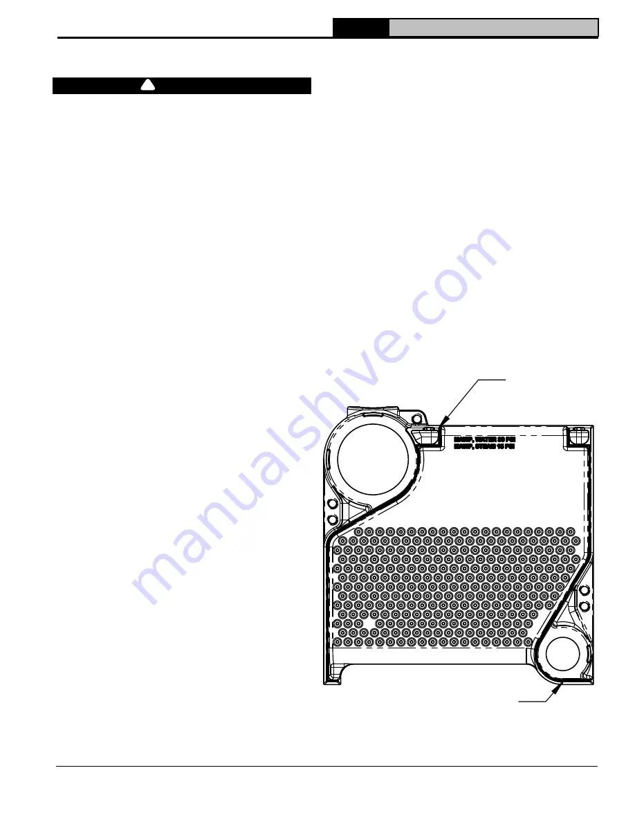
during assembly.
5
Split Section and Base Assembly
See Figures 5-1, 5-2, 5-3 and 3-2 for References.
1. Either left section assembly or right section
assembly can be secured first. Left section
assembly will be secured first for purposes of this
instruction.
NOTICE:
Insulation between base and section
assembly is not used. A high temperature silicone
RTV will be used to seal base/section assembly
joint after section assemblies are joined on base.
See step 19.
2. Screw (2) 5/16-18 hex head bolts,
Item 1
, into
holes in base.
3. Lower left assembly,
Item 2
, onto base with bolts
centered in assembly slots.
4. Tighten 5/16-18 nylon locking nuts and washers,
Item 3
, onto bolts.
5. Thoroughly clean nipples,
Item 4
, and nipple
ports with a de-greasing solvent.
6. Evenly coat nipples and nipple ports with
provided Loctite® 592.
7. Place nipples in nipple ports and bump carefully
with a wooden block to set.
8. Apply provided SIL-BOND RTV 6500 to flue way
joint. See Figure 5-1.
9. Place right section assembly,
Item 5
, onto base
as close to left section assembly as possible
aligning nipples to nipple ports.
10. Screw together enough 3/4-10 x 11" draw rod
using coupling nuts,
Item 6
, to pass through
section assemblies,
Items 2 and 5
, draw plates,
washers & nuts,
Item 7
, on both sides. Two draw
rods are required, one through upper nipple port
and other through lower nipple port.
11. Keep draw rod threads lubricated to reduce
friction for easier assembly.
12. Draw section assemblies together slowly and
evenly. Alternately tighten upper and lower draw
rods. Tighten each draw rod a little at a time so
sections are evenly spaced. Either base assembly
and/or section assemblies may require adjusting
to maintain nipple and nipple port alignments.
13. Tighten until sections meet iron-to-iron. Small
gaps, typically less than 1/16", between sections
after assembly are normal.
NOTICE:
Do not loosen or remove draw rods until
tie rods are secured.
14. Screw (2) 5/16-18 hex head bolts through base
holes and section assembly slots on right side.
15. Tighten 5/16-18 nylon locking nuts and washers
onto bolts.
16. Place 3/8-16 x 7-3/4" long tie rods,
Item 8
, through
top lug holes at upper and lower nipple ports.
17. Tighten 3/8-16 nut and washer,
Item 9
, onto each
end of a tie rod until hand tight. This will allow for
thermal expansion.
18. Remove draw rods.
19. Hydrostatically test section assembly.
NOTICE:
It is essential that hydrostatic testing
be done before sealing block to base (step
20) and before canopy, jacket, controls, and
piping are installed. See Hydro-Test Section for
procedure.
20. Apply provided SIL-BOND RTV 6500 to entire
perimeter of base/section assembly joint. See
Figure 5-2.
Flue Way
Joint
Flue Way
Joint
Figure 5-1: Assembly Section Flue Way Joint
Apply Silicone
Here
Apply Silicone
Here
!


