37
H.
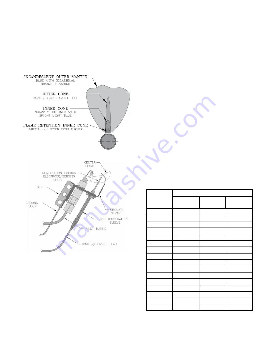
Check pilot burner flame.
See Figure 24. Flame
should be steady, medium hard blue enveloping 3/8 to
½ inch of sensing probe.
I.
Check main burner flame.
See Figure 23. Flame
should have clearly defined inner cone with no yellow
tipping. Orange-yellow streaks should not be confused
with true yellow tipping.
Figure 23: 1 Inch Main Burner Flame
Figure 24: Pilot Burner Flame
J
. Check thermostat operation.
Raise and lower
temperature setting to start and stop boiler operation.
K.
Check ignition control module shut-off.
Disconnect
pilot lead wires from gas valve. If burners do not
shutdown, determine cause of malfunction. Replace
necessary items and check operation.
L.
Check low water cutoff
(if so equipped).
1. Adjust thermostat to highest setting.
2. With boiler operating, open drain valve and slowly
drain boiler.
VIII. SYSTEM START-UP
(continued)
3. Main burners and pilot burner will extinguish and
blower will stop when water level drops below low
water cutoff probe. Verify limit, thermostat or other
controls have not shut off boiler.
4. Adjust thermostat to lowest setting. Refill boiler.
M.
Check limit.
Jumper Thermostat connections in boiler wiring
harness. Allow burners to operate until shutdown by
limit. REMOVE JUMPER.
N.
Adjust gas input rate to boiler.
1. Adjust thermostat to highest setting.
2. Check manifold gas pressure. See Table 5 or rating
label located in the boiler’s vestibule compartment.
Adjust gas valve pressure regulator as necessary
(turn adjustment screw counterclockwise to
decrease manifold pressure, or clockwise to increase
manifold pressure). If pressure cannot be attained,
check gas valve inlet pressure. If less than minimum
indicated in Table 5 or boiler’s rating label, contact
gas supplier for assistance.
3. Clock gas meter for at least 30 seconds. Use Table
10 to determine gas flow rate in Cubic Feet per
Hour.
Seconds
for One
Revolution
Size of Gas Meter Dial
One-Half
Cu. Ft.
One
Cu. Ft.
Two
Cu. Ft.
30
60
120
240
32
56
113
225
34
53
106
212
36
50
100
200
38
47
95
189
40
45
90
180
42
43
86
172
44
41
82
164
46
39
78
157
48
37
75
150
50
36
72
144
52
35
69
138
54
33
67
133
56
32
64
129
58
31
62
124
60
30
60
120
Table 10: Gas Flow Rate in Cubic Feet
Per Hour
Summary of Contents for PVG3
Page 14: ...14 Figure 4 Horizontal Vent Installation III Venting continued...
Page 16: ...16 Figure 7 Attic Offset Figure 6 Vertical Vent Installation III Venting continued...
Page 29: ...29 Figure 17 Wiring Connection Diagram VI Electrical continued...
Page 31: ...31 Figure 19 Circulator Zoned System Wiring Diagram VI Electrical continued...
Page 32: ...32 Figure 20 Zone Valve Zoned System Wiring Schematic VI Electrical continued...
Page 34: ...34 Figure 21 Modular Boiler Piping VII Modular Installation continued...
Page 36: ...36 Figure 22 Operating Instructions VIII System Start up continued...
Page 51: ...51 Figure 29 Flue and Burner Cleanout 1 Burner XI Service continued...
Page 54: ...54 XII Repair Parts continued...
Page 56: ...56 XII Repair Parts continued...
Page 60: ...60 XII Repair Parts continued...
Page 67: ...67 SERVICE RECORD DATE SERVICE PERFORMED...
Page 68: ...68 U S Boiler Company Inc P O Box 3020 Lancaster PA 17604 1 888 432 8887 www usboiler net...


