


32
103536-13 - 2/24
MegaSteam
Installation & Service Manual
c. Abandoned Openings – Openings through
the chimney wall that are no longer used
shall be sealed in accordance to NFPA 211.
Often abandoned openings are improperly
sealed and usually covered by a gypsum wall
covering.
d. Clean Chimney – Chimney shall be free of all
loose debris.
5. Draft Regulator – the draft regulator supplied with
the boiler (or equivalent) must be used with this
appliance. Refer to Figures 5-1 and 5-2.
B. CHIMNEY CONNECTOR
1. A chimney connector (vent pipe) is used to
connect the boiler to the base of the chimney.
The chimney connector should be kept as short
as possible. The horizontal length of the chimney
connector shall not be greater than 10 feet.
NOTE: Secure chimney connector to cast iron
smokebox collar with three (3) #10 x ½ in.
self drilling hex head TEK screws provided in
miscellaneous parts carton. Locate screws
around perimeter of connector as shown in Figure
5-2 and approximately ½ in. in from edge. Use
drill with 5/16 in. hex bit to drive screws through
connector and smokebox collar.
DANGER
The chimney and connector shall be inspected
annually for signs of debris and corrosion.
Loose mortar at the base of the chimney may be
a sign of condensate damage to the chimney.
A chimney professional shall be contacted
immediately to examine the damage and
recommend a solution. Long term operation
while in this condition may cause a venting
failure and force flue gases into the living
space. If the chimney is to be re-lined use the
recommendations in NFPA 31, Appendix E or
CSA B139.
2. Vent Connector shall be any of the following
and of the same size as the outlet of boiler.
a. Type L or a factory built chimney material
that complies with the Type HT requirements
of ANSI/UL 103. Install in accordance with
listing and manufacturer’s instructions.
b. Steel pipe having resistance to corrosion
and heat with a minimum wall thickness of
24 Gauge (0.024 in.).
DANGER
Any signs of condensate seepage at the base
of the chimney shall be inspected immediately.
The discoloration may be a sign of chimney
damage and must be remedied immediately.
C. DRAFT
1. The natural draft generated through a chimney is
dependent on several factors including, chimney
height, temperature of flue gases, cross section
area of chimney, chimney wall insulation value,
dilution air and total volume of flue gases, to
name a few. Make sure that the boiler has been
running for at least 5 minutes before measuring
the draft.
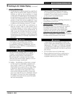
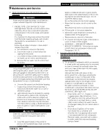
2. Minimum Draft at Breech (Canopy) – The draft
induced by a chimney must create at least a
pressure of 0 (zero) inches water column (“ w.c.)
at the pressure tapping on the canopy mounted
on rear of boiler (see Figure 5-3). The pressure
at the canopy cannot be positive since this could
create a condition that allows flue gas by-products
to escape from the draft regulator. A negative
pressure reading up to -.03 inches water column
is acceptable for proper operation. (See Table
12-1) Burner Specifications at the rear of this
manual for more details).
3. Minimum Overfire Pressure – The overfire
pressure is another piece of information that is
often measured, however this should be done for
observation purposes only! The breech pressure
must be used to qualify the draft condition. See
Table 12-1 for more details as a guide. Actual
draft and temperature measurements may be
different then those values in the table.
Figure 5-3: Smokebox Pressure Tapping for
Checking Draft at Breech
5
Venting & Air Intake Piping
(continued)
!
!


