background image

USER GUIDE

Parts

Parts

U-3018CLRINT-40C

Item

Description

U-Line P/N

1

ANTI TIP BRACKET W/SCREWS

80-54012-00

2

BACK PANEL

80-54142-00

3

CIRCULATION PUMP

80-54137-00

4

CLEAR ICE MACHINE CLEANER *

ULACLRCLEAN

5

COMPRESSOR ASSY, R600

80-54376-01

6

CONDENSER ASSEMBLY

80-54079-00

7

CONDENSER FAN BLADE

80-54066-00

8

CONDENSER FAN MOTOR

80-54138-00

9

COVER PUMP, BLACK

80-54073-00

10

COVER W/HOOK, BLACK

80-54072-00

11

DOOR ASSEMBLY W/O HINGES

80-54148-00

12

DISPLAY MODULE

80-54032-00

13

DRAIN PUMP, ICE MACHINE

80-54147-00

14

DRAIN TUBE, CLEAR

80-54074-00

15

DRIER

80-54055-00

16

LED LIGHT STRIP AND COVER ASSY

80-54000-00

17

EVAPORATOR ASSEMBLY

80-54063-00

18

GASKET, DOOR, INJECTION MOLDED

80-54003-00

19

GASKET, HORIZONTAL

80-54061-00

20

GRILLE W/SCREWS

80-54031-00

21

HI TEMP THERMISTOR *

80-54070-00

22

HINGE COVER(2 PCS)

80-54001-00

23

HINGES(2) W/SCREWS AND COVERS

80-54013-00

24

HINGE MOUNTING HOLE COVERS(4)

80-54024-00

25

HOT GAS VALVE AND COIL

80-54169-00

26

ICE SCOOP, CLR

80-54080-00

27

LEG LEVELERS(4)

80-54019-00

28

MAIN BOARD(NO CASE OR WIRES)

80-54008-00

29

PACKAGING *

80-54143-00

30

POWER CORD *

80-54144-01

31

PREFORMED DISPERSION TUBE

80-54128-00

32

REED SWITCH **

80-54134-00

33

STAND PIPE

80-54077-00

34

THERMISTOR(1 PC)

80-54006-00

35

THERMISTOR COVER AND PIN

80-54023-00

36

WATER DISPERSION RECEPTACLE

80-54078-00

37

WATER LINE ASSEMBLY

80-54068-00

38

WATER TROUGH, BLACK

80-54075-00

39

WATER VALVE ASSEMBLY

80-54139-00

40

WIRE HARNESS, BOARD *

80-54342-01

* NOT PICTURED

** REED SWITCH LOCATED BEHIND DISPLAY

2

1

3

9

10

11 18 19

12

14

16

17

20

22 23

24

26

27

31

33

36

38

35

34

5

6

7

8

15

25

37

39

28

13

42

Summary of Contents for U-3018CLRINT-40C

Page 1: ...USER GUIDE SERVICE MANUAL Model U 3018CLRINT 40C...

Page 2: ...p Drain General Installation Integrated Panel Dimensions Grille Installation Integrated Panel Installation Door Swing Door Stop Door Adjust Maintenance Cleaning Cleaning Condenser Extended Non Use Ope...

Page 3: ...HT PRODUCT RIGHT PLACE RIGHT TEMPERATURE PRODUCT INFORMATION Looking for additional information on your product User Guides Spec Sheets CAD Drawings and Product Warranty information are available digi...

Page 4: ...oderate personal injury property or equipment damage This unit contains R600a Isobutane which is a flammable hydrocarbon It is safe for regular use Do not use sharp objects to expedite defrosting Do n...

Page 5: ...e so children may not easily climb inside If the unit is being removed from service for disposal check and obey all federal state and local regulations regarding the disposal and recycling of refriger...

Page 6: ...ures may reduce the unit s ability to reach low temperatures and or reduce ice production on applicable models For best performance keep the unit out of direct sunlight and away from heat generating e...

Page 7: ...it Always keep your working area dry NOTICE Electrical installation must observe all state and local codes This unit requires connection to a grounded three prong polarized receptacle that has been pl...

Page 8: ...like to align the face of the unit with other adjacent cabinet doors you may need to alter the wall just behind the drain connection on the unit to accommodate the drain CUTOUT DIMENSIONS PRODUCT DIM...

Page 9: ...ide Each door can be opened individually one at a time without interference However to ensure unobstructed door swing opening both doors at the same time 1 4 6 4 mm of space needs to be maintained bet...

Page 10: ...the cold water supply The water pressure should be between 20 and 120 psi 138 and 827 kPa The water line MUST have a shut off valve on the supply line CAUTION Do not use tape or joint compound when at...

Page 11: ...ETY INSTALLATION INTEGRATION OPERATING INSTRUCTIONS MAINTENANCE SERVICE 4 On the back panel exit waterline in same location as drain line 5 Turn on water supply and check for leaks 6 Reinstall back pa...

Page 12: ...e unit Unit has a solid base that will not allow the unit to drain below itself There is a possibility that hose connections may have loosened during shipment Verify all connections and fittings are f...

Page 13: ...installed drain pump If you need to install a drain pump into your unit see DRAIN PUMP section in the User Manual To order a drain pump order part number ULADRAINPUMP115V online at u line com See bel...

Page 14: ...ing s rear height Shorten the unit height in the front by adjusting the front legs This allows the unit to be gently tipped into the opening Readjust the front legs to level the unit after it is corre...

Page 15: ...ensure that all drilled holes are drilled to the correct depth in order to avoid splits in the wood when hardware is installed 1 Cut the panels to the dimensions listed in the diagram below 2 Optiona...

Page 16: ...1 2 876 mm to the underside of the counter to leave room for leveling adjustments A single prepared panel with insert must not weigh more than 20 lbs 10 kg Integrated Panel Preparation 1 Cut the main...

Page 17: ...Dimensions 3 4 20 mm 28 13 16 732 mm 2 3 4 70 mm 2 3 4 70 mm R 5 8 R 16 mm 1 8 3 mm 1 4 6 mm Wooden Insert Notch Depth 1 8 3 mm 2 3 8 60 mm 7 8 22 mm Ref Top Detail Insert Notch Top Design 1 8 3 mm 3...

Page 18: ...h more than 20 lbs 10 kg It is important to ensure that all drilled holes are drilled to the correct depth in order to avoid splits in the wood when hardware is installed Appliance will need up to 34...

Page 19: ...0 33 7 8 762 mm 860 mm A minimum of 1 25 mm is required from the floor to the bottom of the extended integrated panel frame for proper ventilation Integrated Grille If you would like to cover the gri...

Page 20: ...ur grille height 2 Finish or stain your grille panel to match your surrounding furniture Finish front back and edges to prevent warping Carefully follow the manufacturer s recommendations for finish a...

Page 21: ...ill 6 pilot holes into the wood panel 1 2 12 mm deep using the holes in the door frame as a guide NOTICE It is important to ensure that all drilled holes are drilled to the correct depth in order to a...

Page 22: ...ust be installed Do NOT touch the condenser fins The condenser fins are SHARP and can be easily damaged Removing the grille 1 Disconnect power to the unit 2 Remove the three screws 1 3 Remove grille 2...

Page 23: ...l space for any knobs or pulls installed on the integrated panel frame Stainless Steel models that are installed adjacent to a wall require 2 1 4 57 mm door clearance on hinge side to allow for door h...

Page 24: ...90 2 Slide hinge pin into hole as shown Pin should slide into place stopping the door at 90 if the pin does not go into the hole shown hold the door less than 90 open and try again 3 To fully seat th...

Page 25: ...ch pair of Torx head screws both the upper and lower hinge plates 3 Square and align door as necessary 4 Tighten Torx head screws on hinge 5 Reinstall gasket into the channel starting at the corner RE...

Page 26: ...ecommends discarding the ice produced during the first two to three hours of operation to avoid possible dirt or scale that may dislodge from the water line When plugged in the unit will begin operati...

Page 27: ...Hours or On 24 Hours 4 To exit press or simply wait for the menu to time out CUSTOMER MENU The 3000 Series of U Line undercounter refrigeration appliances contains a feature rich customer menu The Cus...

Page 28: ...ation 3 To return to the Customer Menu press and select Return to Menu Energy Saver Mode Energy Saver mode reduces overall energy consumption by reducing the amount of ice stored in the bin along with...

Page 29: ...High Medium Low and Off To select a new tone level enter the Sound Level Menu from the Customer Menu 1 Press or to select the current sound level 2 Press The current setting will begin to flash 3 Pres...

Page 30: ...aking cycle is complete After 3 hours in Silent Mode normal ice production will continue NOTE Silent Mode will not silence any alerts To initiate Silent Mode enter Silent Mode Menu from within the Cus...

Page 31: ...PERATING INSTRUCTIONS MAINTENANCE SERVICE Help To access the Help Menu select Help from the Customer Menu Press or to scroll through available information To return to the Customer Menu press to selec...

Page 32: ...to 12 7 mm in depth A fuller cube with less of a dimple results in a thicker ice bridge As the ice bridge thickens the tendency for the cubes to stay together as a slab increases A bridge thicker than...

Page 33: ...INSTALLATION INTEGRATION OPERATING INSTRUCTIONS MAINTENANCE SERVICE Airflow and Product Loading NOTICE The unit requires proper airflow to perform at its highest efficiency Do not block the front gri...

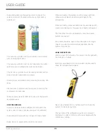
Page 34: ...appropriate treatment Wear rubber gloves and safety goggles and or face shield when handling Ice Machine Cleaner Clean surfaces with a mild detergent and warm water solution Do not use solvent based...

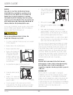
Page 35: ...for 5 seconds 9 When water begins flowing over the evaporator approximately 3 minutes pour 1 2 oz of Clear Ice Machine Cleaner into the water trough The cleaning process will last approximately 45 mi...

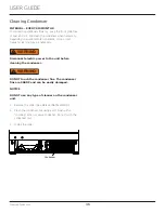
Page 36: ...frequent cleaning may be necessary Disconnect electric power to the unit before cleaning the condenser DO NOT touch the condenser fins The condenser fins are SHARP and can be easily damaged NOTICE DO...

Page 37: ...st remain open to prevent formation of mold and mildew Open door a minimum of 2 50 mm to provide the necessary ventilation WINTERIZATION If the unit will be exposed to temperatures of 40 F 5 C or less...

Page 38: ...h a brief description of the normal operating sounds they make NOTE Your product may not contain all the components listed Compressor The compressor makes a hum or pulsing sound that may be heard when...

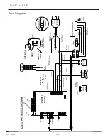
Page 39: ...T RELAY EMBRACO COMPRESSOR GREEN W YELLOW GROUND PINK LIGHT BLUE HOT WHITE 115V DARK BLUE 220 240V WHITE 115V DARK BLUE 220 240V PURPLE PUMP BLACK 115V BROWN 220 240V FAN 115 VOLT PLUG CONTROL BOARD B...

Page 40: ...replace the part in question The part that caused the damage must be returned to U Line in its entirety The part must be clearly labeled with the serial number of the unit it was removed from the dat...

Page 41: ...r warranty labor Units must be registered prior to warranty submittal Customers may register at www U Line com A proof of purchase is required We also accept the following information to update warran...

Page 42: ...SKET HORIZONTAL 80 54061 00 20 GRILLE W SCREWS 80 54031 00 21 HI TEMP THERMISTOR 80 54070 00 22 HINGE COVER 2 PCS 80 54001 00 23 HINGES 2 W SCREWS AND COVERS 80 54013 00 24 HINGE MOUNTING HOLE COVERS...

Page 43: ...ranty status Please provide the model serial number part number and part description Some parts will require color or voltage information If U Line requires the return of original parts we will inform...

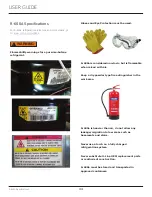
Page 44: ...ust observe all federal state and local laws regarding refrigerants Gloves and Eye Protection must be used R 600a is considered non toxic but is flammable when mixed with air Keep a dry powder type fi...

Page 45: ...pump and recovery equipment should be at least 10 feet from the work area It is recommended that a simple LPG gas detector is on site during service Ensure that all R 600a is removed from the system p...

Page 46: ...is left within the system prior to repair simple venting is not sufficient Evacuate and charge with dry nitrogen for leak checks Repair leaks or replace system parts as required When re brazing the sy...

Page 47: ...ll a Schrader Type access port on the compressor process stub Evacuate the system to 100 microns prior to charging Weigh in the R 600a charge using a refrigerant scale run compressor an extra two minu...

Page 48: ...cold near inlet Outlet below room temperature Lower than normal Partial Restriction Somewhat lower than normal vacuum Warm near room temperature Very hot Top passes warm Lower passes cool near room te...

Page 49: ...re not hot or frozen Do not touch a bare circuit board unless you are wearing an anti static wrist strap that is grounded to an electrical ground or grounded water pipe Handle circuit boards carefully...

Page 50: ...improper use maintenance installation service repair acts of God fire flood or other natural disasters The product must be installed operated and maintained in accordance with your product s User Guid...

Reviews: