background image

www.U-LineService.com

6

02/2005

BI-98 Ice Maker

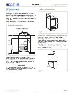
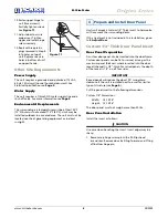
10. Fasten upper hinge to 

unit (three screws). 
Partially tighten screws. 
See 

Figure 11

.

11. Adjust door to assure 

proper seal. Tighten 
upper and lower hinge 
screws securely. 

12. Replace three plastic 

plugs removed in Step 8 
into holes on top of 
unit. Replace screws in 
holes in bottom of unit 
on opposite side.

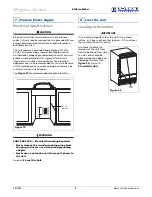
Other Site Requirements

Power Supply

The unit requires a grounded and polarized 115 VAC, 
60 Hz, 15A circuit (normal household current). See 
Electrical Specifications on 

Page


9

.

Water Supply

The unit requires a 1/4-inch OD water supply line and a 
shut-off valve. For more information see 

Page 8

.

Environmental Requirements

The surrounding air temperature must be at least 50°F 
(10°C) but must not exceed 110°F (40°C). Units may be 
installed outdoors in a covered area. The unit must not be 
located near heat-generating equipment or in direct 
sunlight.

Units will accept a Custom 1/4" Thick Insert to harmonize 
with or accent the surrounding decor. 

If this treatment is not included in this installation, go on 
to 

5 Adjust Door

.

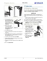
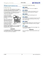
Custom 1/4" Thick Door Panel Insert

Door Panel Preparation

A custom door panel can be inserted into the doorframe. 
Custom door panels can be flat or raised, as long as the 
maximum panel thickness where inserted into the door 
reveal (channel) is 1/4"-thick. For raised panels, the depth 
of the reveal is 1/4" on all four sides.

IMPORTANT

Raised panels will reduce the door’s 90° swing/zero 
clearance if the unit is installed next to a wall or similar 
type of structure (see 

Page 4

).

Cut the panel insert to the following dimensions.

Custom 1/4" Dimensions:

Width:

13-15/16"

Height:

15-15/16"

The door panel must not weigh more than 20 lbs.

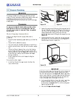
Door Panel Installation

Install the insert as follows:

CAUTION

Use care when handling the insert. Insert edges may be 
sharp.

1. Remove top hinge screw pin with a Phillips head 

screwdriver. Remove door by tilting forward and lifting 
off bottom hinge pin.

Figure 11

4 Prepare and Install Door Panel

Summary of Contents for Origins BI-98

Page 1: ...LineService com Phone 414 354 0300 FAX 414 354 7905 Service Parts Tech Lines Phone 800 779 2547 FAX 414 354 5696 OnlineService U Line com 2005 U Line Corporation 02 2005 BI 98 Ice Maker Installation...

Page 2: ...oper hook up can result in substantial property damage If you are unsure of your ability to safely connect the water supply to the unit consult a licensed plumber for assistance This unit requires con...

Page 3: ...and water connection parts Complete and mail the Product Registration Card or register online at www U LineService com Once your unit is installed keep the User Manual and this Installation Guide in a...

Page 4: ...unit sits on a level surface as it does not have feet levelers If it is not level the ice mold will not fill evenly Product Dimensions Door Swing Clearances Information Units have a zero clearance fo...

Page 5: ...talled Align hinge outer edge with cabinet before tightening screws 5 Relocate plastic spacer bushing on bottom of door to opposite side and place door on bottom hinge pin See Figure 8 Clean out bushi...

Page 6: ...t Units will accept a Custom 1 4 Thick Insert to harmonize with or accent the surrounding decor If this treatment is not included in this installation go on to 5 Adjust Door Custom 1 4 Thick Door Pane...

Page 7: ...g Door Alignment The unit s door is aligned at the factory before shipment However its alignment could have been disturbed during shipment or during door panel installation IMPORTANT Properly aligned...

Page 8: ...he use of copper tubing for installation To connect to water supply 1 Install the 1 4 inch OD copper water line from the main water source 2 Locate the compression fitting and ferrule packed with the...

Page 9: ...to nuisance tripping However be sure to consult your local codes See Figure 19 for recommended receptacle location WARNING SHOCK HAZARD Electrical Grounding Required Never remove the round grounding p...

Page 10: ...lle itself It is located toward the top of the middle recessed section of the grille 3 Place the two hook hinges located on the rear bottom side of the grille onto the front lip of the unit base Swing...

Page 11: ...bin arm is locked the unit will maintain temperature for ice storage IMPORTANT It is possible that dirt or scale will dislodge in the water line Always throw away all ice cubes made during the first t...

Page 12: ...U Line has distinguished itself as the leader in built in undercounter ice making refrigeration and wine storage appliances Who to Call Service Information If the need for service arises contact the d...

Reviews: