PAGE 9 OF 39
0318 IH-7095
OPERATION CONTINUED
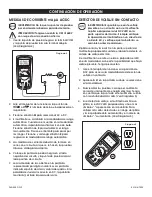
LoZ AC VOLTAGE MEASUREMENTS
When the function switch is turned to the LoZ position,
the meter applies a low input impedance circuit to
the input terminals to eliminate stray or ghost voltages.
Refer to the voltage measurements section earlier in this
guide for safety information and connection diagrams.
1. Insert the black test lead banana plug into the
negative (COM) jack and the red test lead banana
plug into the positive (V/
Ω
) jack.
2. Move the function switch to the Lo Z position.
3. Touch the test probe tips to the circuit under test.
4. The meter defaults to the auto range mode (
Auto
displayed on LCD). Manual range cannot be used
in this mode.
5. Read the digital value of the measurement in the
display. The display will also indicate the proper
decimal point and measurement type/units symbols.
VARIABLE FREQUENCY VOLTAGE
MEASUREMENTS
When the function switch is turned to the LPF position
the meter can measure voltage on signals with varying
frequency as in variable frequency drives (VFD). Refer to
the voltage measurements section earlier in this guide
for safety information and connection diagrams.
1. Insert the black test lead banana plug into the
negative (COM) jack and the red test lead banana
plug into the positive (V/
Ω
) jack.
2. Move the function switch to the LPF position.
3. Select AC voltage.
4. Press and hold the
LPF
button for two seconds. The
meter will beep and the LPF icon will appear on the
display.
5. Touch the test probe tips to the circuit under test.
6. The meter defaults to the auto range mode. Manual
range cannot be used in this mode.
7. Read the digital value of the measurement in the
display. The display will also indicate the proper
decimal point and measurement type/units symbols.
DIODE TEST
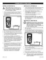
1. Insert the black test lead banana plug into the
negative (COM) jack and the red test lead banana
plug into the
positive jack. (See Figure 8)
2. Turn the function switch to
position. Use the
M
button to select the diode function if necessary (the
diode and voltage symbols will appear on the LCD
when in diode test mode).
3. Touch the test probe tips to the diode or
semiconductor junction under test. Note the meter
reading.
4. Reverse the test lead polarity by reversing the red
and black leads. Note this reading.
5. The diode or junction can be evaluated as follows:
• If one reading displays a value (typically 0.400V
to 0.900V) and reverse reading displays OL, the
diode is good.
• If both readings display OL, the device is open.
• If both readings are very small or O, the device is
shorted.
HZ AND % DUTY CYCLE TEST
Hz and Duty cycle % are available in the AC Voltage or
AC current functions or can be selected directly in the
Hz% position of the function switch. Follow the AC voltage
or AC current procedures for operational details.
NOTE: Duty cycle measurements are AC only
for this meter. Measurement signals must be
"zero crossing" and must reach -0.7V for the
meter to properly display duty cycle percent.
Figure 8


