


PAGE 7 OF 39
0318 IH-7095
mA/μA AC/DC CURRENT MEASUREMENTS
WARNING! Do not handle the test leads above
the finger/hand guard barrier.
CAUTION! Observe CAT III 600V with respect to
earth ground.
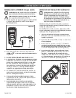
1. Insert the black test lead into the COM terminal and
the red test lead into the
mA/μA
terminal. (See Figure 4)
2. Turn the meter’s function switch to the
or
position. The
mA
or
μA
symbol will appear on the
display.
3. Press the
M
button to select AC or DC.
4. The meter defaults to the auto range mode. When in
auto mode, the display shows the
Auto
icon. Press
the
R
button to manually range the meter. Press the
R
button to step through the ranges. Press and hold
the
R
button to return to the auto range mode.
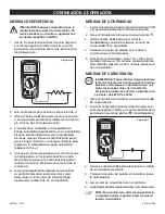
5. Current measurements must be taken in series with
the circuit under test. See accompanying diagram.
6. Touch the black test lead to the negative side of the
circuit and the red test lead to the positive side of
the circuit.
7. Read the current measurement in the display
represented by numerical digits. The display will
indicate the proper decimal point and value. In
DC, if the polarity is reversed, the display will show (-)
minus before the value.
NON-CONTACT VOLTAGE DETECTOR
WARNING! It is possible for voltage to be
present in a circuit, even if the meter does not
beep or flash the NCV LED lamp at the top of
the meter. Always verify meter operation on a
known live AC current circuit, and verify that
the batteries are fresh before use.
The audible beep sounds and the LED lamp at the top
of the meter flashes when the meter senses an electrical
voltage field.
If the meter does not emit a tone or flash the LED in this
mode, there is still the possibility that voltage is present.
Use caution.
1. Turn the function switch to the NCV position to
access the non-contact voltage detect mode.
2. EF is displayed when in this mode is selected.
3. To test, place the meter near a source of electrical
energy. Note that the tip of the meter offers the
highest sensitivity. (See Figure 5)
4. If a voltage is detected, the meter will beep, the
NCV LED will flash and one or more "-" symbols will
appear on the display. For higher detected voltages,
the beep and flash rate will increase and the
number of "-" symbols will increase. (See Figure 5)
OPERATION CONTINUED
Figure 4
Figure 5