


LARA-R2 series - System Integration Manual
UBX-16010573 - R02
Objective Specification
System description
Page 19 of 148
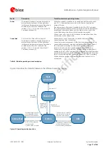
1.5.1.1
VCC supply requirements
Table 6 summarizes the requirements for the
VCC
module supply. See section 2.2.1 for all the suggestions to
properly design a
VCC
supply circuit compliant to the requirements listed in Table 6.
VCC supply circuit affects the RF compliance of the device integrating LARA-R2 series modules
with applicable required certification schemes as well as antenna circuit design. Compliance is
guaranteed if the VCC requirements summarized in the Table 6 are fulfilled.
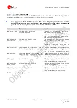
Item
Requirement
Remark
VCC
nominal voltage
Within
VCC
normal operating range:
3.30 V min. / 4.40 V max
RF performance is guaranteed when
VCC
PA voltage is
inside the normal operating range limits.
RF performance may be affected when
VCC
PA voltage is
outside the normal operating range limits, though the
module is still fully functional until the
VCC
voltage is
inside the extended operating range limits.
VCC
voltage during
normal operation
Within
VCC
extended operating range:
3.00 V min. / 4.50 V max
VCC
voltage must be above the extended operating
range minimum limit to switch-on the module.
The module may switch-off when the
VCC
voltage drops
below the extended operating range minimum limit.
Operation above
VCC
extended operating range is not
recommended and may affect device reliability.
VCC
average current
Support with adequate margin the highest averaged
VCC
current consumption value in connected-mode
conditions specified in
LARA-R2
series Data Sheet
The highest averaged
VCC
current consumption can be
greater than the specified value according to the actual
antenna mismatching, temperature and
VCC
voltage.
for connected-mode current profiles.
VCC
peak current
Support with margin the highest peak
VCC
current
consumption value in connected-mode conditions
specified in
LARA-R2
series Data Sheet
The specified highest peak of
VCC
current consumption
occurs during GSM single transmit slot in 850/900 MHz
connected-mode, in case of mismatched antenna.
See
1.5.1.2 for 2G connected-mode current profiles.
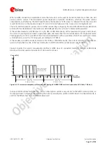
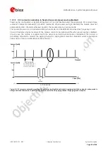
VCC
voltage drop
during 2G Tx slots
Lower than 400 mV
VCC
voltage drop directly affects the RF compliance with
applicable certification schemes.
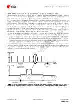
Figure 5 describes
VCC
voltage drop during Tx slots.
VCC
voltage ripple
during 2G/LTE Tx
Noise in the supply has to be minimized
VCC
voltage ripple directly affects the RF compliance with
applicable certification schemes.
Figure 5 describes
VCC
voltage ripple during Tx slots.
VCC
under/over-shoot
at start/end of Tx slots
Absent or at least minimized
VCC
under/over-shoot directly affects the RF compliance
with applicable certification schemes.
Figure 5 describes
VCC
voltage under/over-shoot.
Table 6: Summary of VCC supply requirements


