


‐
18
‐
2.3
PROGRAMMING
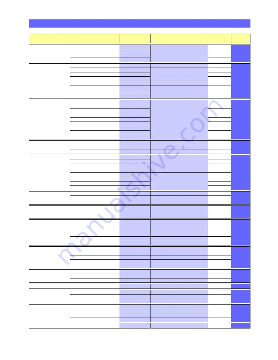
PARAMETERS
LIST
Menu
Group
Parameter
Enter
Parameter
No.
Enter
the
following
data…
Default
Setting
See
Section
Load
Defaults
and
Parameter
Check
Load
Defaults
#000
Enter
the
required
default
parameter
followed
by
#
N/A
2.3.1
Load
System Defaults
#001
N/A
Load
Radio
Defaults
#002
N/A
Check
Parameters
#003
N/A
Audio
Settings
GSM
Mode
#004
0#
=
Disable
or
1#
=
Enable
Disabled
2.3.2
Siren
Volume
#005
Enter
0
to
5
followed
by
#
0#
=
off,
1#
=
min
volume
to
5#
=
max
volume
Level 3
Audio
Volume
#006
Level
3
Ring
Volume
#007
Off
Audio
Mode
#008
0#
=
Simplex
or
1#
=
Half
Duplex
Half
Duplex
Mains
Disconnection
Alert
#009
0#
=
Disable
or
1#
=
Enable
Enabled
Assurance
Tone
#010
Enabled
Telephone
Line
Fail
Alert
#011
Enabled
Hardwired
Inputs
Pullcord
#012
Enter
hardwired
input
device
type
parameter
followed
by
#
For
BS8521
protocol
add
the
2
digit
Location
Code
from
the
list
on
page
15
before
pressing
#
E.g.
a
heat
detector
in
the
kitchen
on
a
hardwired
input
would
be
#019
22#
None
2.3.3
Smoke
#013
None
PIR
Movement
Sensor
#014
None
Door
Exit
#015
None
High
Temperature
#016
None
Low
Temperature
#017
None
Gas
#018
None
Heat
#019
None
Carbon
Monoxide
#020
None
Identity
Settings
Protocol
Type
#022
0#
=
TT or 1#
=
BS8521
TT
2.3.4
Unit
ID
(max
12
digits)
#024
Enter
the
unit
ID
followed by
#
995
Pre
‐
Alarm
Delay
(in
4
sec
steps)
#025
00#
no
delay
to
60#
max
4
Seconds
Telephone
Numbers
Tel
No.
1
(ARC
1)
#026
Enter
the
Control
Centre
Tel
No.
(max
16
digits)
followed
by
#
None
2.3.5
Tel
No.
2
(ARC
2)
#027
None
Tel
No.
3
(ARC
3)
#028
None
Tel
No.
4
(ARC
4)
#029
None
Tel
No.
5
(PR
1)
#030
Enter
the
Personal
Recipient
Tel
No.
(max
16
digits)
followed
by
#
None
Tel
No.
6
(PR
2)
#031
None
Tel
No.
7
(PR
3)
#032
None
Tel
No.
8
(PR
4)
#033
None
Activity
Monitoring
Enable/Disable
#034
0#
=
Disable
or
1#
=
Enable
Disabled
2.3.6
12
or
24
Hour
Period
and
Threshold
Count
#035
1
st
digit:
0
=
12Hr
&
1
=
24Hr
2
nd
digit:
=
threshold
(0
to
9)
then
#
12
Hour
Threshold
1
Periodic
Test
Interval
(01
‐
99
days)
Enable/Disable
+0
Hours
or
+12
Hours
#036
1
st
2
digits
=
interval
in
days
3
rd
digit:
0
=
Disable
1
=
Enable
4
th
digit:
0
=
+0Hrs
1
=
+12Hrs
then
#
Disabled
2.3.7
Dial
‐
out
Routine
Dial
Sequence
#037
Enter
the
telephone
number
dial
sequence
followed
by
#
(8
digits)
None
2.3.8
Dial
Attempts
(1
to
9)
#038
Enter
the
number
of
dial
attempts
at
each
tel
number
followed
by
#
4
Safe
Call
Device
Option
#039
0#
=
Disable
or
1#
=
Enable
Disabled
Caller
Party
Disconnect
#048
0#
=
Disable
or
1#
=
Enable
Disabled
Radio
Devices
Manual
Learn
Radio
Device
#040
Enter
8
digit
ID,
followed
by
2
digit
location
code,
followed
by
#
N/A
2.3.9
Manual
Delete
Radio
Device
#041
Enter
8
digit
ID
followed
by
#
N/A
Auto
‐
Learn
Radio
Device
and
assign
a
Location
Code
#050
Activate
device,
enter
2
digit
location
code,
followed
by
#
N/A
Personal
Recipient
Message
Record
ID
Message
#060
Record
PR
Message
(8
secs
max)
N/A
2.3.10
Play
ID
Message
#061
Listen
to
PR
Message
N/A
Delete
ID
Message
#062
Press
#
to
Delete
N/A
Intruder
Mode
Enable/Disable
#063
0#
=
Disable
or
1#
=
Enable
Disabled
2.3.11
Pushbutton
Settings
Red
Emergency
Button
#064
0#
=
Disable
or
1#
=
Enable
Enabled
2.3.12
Yellow
Function
Button
#065
0#
=
Disable
or
1#
=
Enable
Enabled
Green
Cancel
Button
#066
0#
=
Disable
or
1#
=
Enable
Enabled
LED
Settings
Red
Emergency
Button
LED
#067
0#
=
Disable
or
1#
=
Enable
Enabled
2.3.13
Tri
‐
Colour
Status
LED
#068
0#
=
Disable
or
1#
=
Enable
Enabled
Yellow
Function
Button
LED
#069
0#
=
Disable
or
1#
=
Enable
Disabled
Green
Cancel
Button
LED
#070
0#
=
Disable
or
1#
=
Enable
Disabled
Security
Code
Change
Security
Code
#125
Enter
new
4
digit
code
followed
by
#
1670
2.3.14


