
‐
5
‐
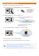
DO NOT
UNPLUG
OR
SWITCH OFF
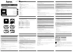
Manufactured in the UK by
REN 1.0
Receiver Frequency 169.48125MHz
Complies with:
ECC/DEC/(05)02
ETSI EN 300 220-2 Class 1
a 1
b 2
c 3
d 4
e 5
f 6
g 7
h 8 No user serviceable parts inside case.
8
5
2
0
*
1
4
7
#
3
6
9
tynetec
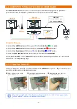
1.4
CONNECTING
THE
REACH
PLUS GSM
AT
‐
HOME
ALARM
The
Reach
Plus
GSM
at
‐
home
alarm
unit
should
only
be
installed
and
programmed
by
trained
personnel.
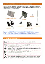
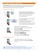
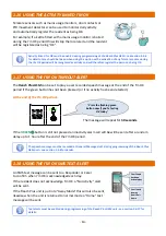
Connect
the
GSM
Base,
GSM
antenna
and
power
lead
as
shown
below;
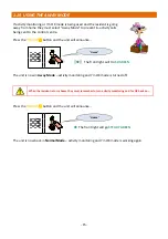
Connection
Procedure...
1.
Connect
the
GSM
Base
lead
with
the
green
to
the
Reach
Plus
C/O
socket.
2.
Connect
the
GSM
Base
lead
with
the
red
to
the
Reach
Plus
DATA
socket.
3.
Connect
the
Power
Lead
with
the
blue
to
the
Reach
Plus
SUPPLY
socket.
4.
Screw
the
GSM
Antenna
into
the
brass
socket
on
the
side
of
the
GSM
Base
.
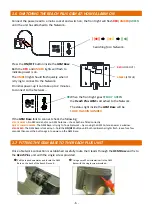
Do
not
fix
the
GSM
Base
to
the
Reach
Plus
until
it
has
been
powered
‐
up
and
a
Network
connection
is
established
–
see
the
following
page.
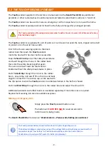
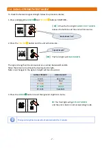
1.5
FITTING
THE
SIM
CARD
A
2G
mini
SIM
card
is
normally
supplied
and
fitted
in
the
GSM
Base
by
Tynetec
–
if
you
need
to
fit
your
own
SIM
card
follow
the
steps
illustrated
below;
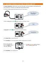
If
you
intend
using
Tynetec’s
iCare
lifestyle
monitoring
service
then
the
SIM
card
must
be
provided
by
Tynetec
as
it
uses
a
secure
private
network
to
carry
the
data.
Reach
Plus
AT
‐
HOME
ALARM
UNIT
GSM
BASE
GSM
ANTENNA
MAINS
ELECTRICITY
SUPPLY
POWER
LEAD
C/O
DATA
SUPPLY
IMPORTANT
This
aerial
wire
receives
signals
from
radio
devices
and
must
not
be
cut
‐
down
or
coiled
‐
up
NOTE
The
TEL
socket
is
not
used
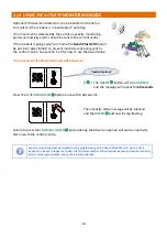
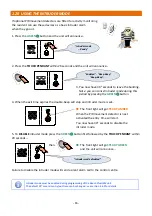
Slide
the
SIM
carrier
door
to
the
right
and
hinge
open…
Insert
the
SIM
card
into
the
carrier
door
as
shown
below…
Close
the
carrier
door
and
slide
to
the
left
until
it
clicks
‐
shut…
Notched
corner
on
SIM
card
Click
shut
Open
door
Summary of Contents for Reach plus GSM
Page 46: ...46 NOTES...