Code Alarm ca 1051, Installation Manual
The Code Alarm ca 1051 is a cutting-edge alarm system designed to provide secure protection for your vehicle. Ensure a seamless installation by following step-by-step instructions provided in the comprehensive Installation Manual. Download this manual for free from our website to optimize your experience with this exceptional product.
Share
Download


Reviews:
No comments
Related manuals for ca 1051

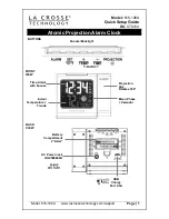
WT-5120
Brand: La Crosse Technology Pages: 11

VA1
Brand: La Crosse Technology Pages: 18
616-146A
Brand: La Crosse Technology Pages: 6
513-1417BS
Brand: La Crosse Technology Pages: 12
Soluna C79141
Brand: La Crosse Technology Pages: 8

Excalibur AL-700LC
Brand: Omega Pages: 10

Evolution-Advanced EV-DP
Brand: Nittan Pages: 7

EL6117 White
Brand: Easylife Pages: 2

WU1FR9-FFP
Brand: OttLite Pages: 53

1285
Brand: Kidde Pages: 7

RPOSTAR Gold
Brand: A1TECH Pages: 12

TWO magic
Brand: philippi Pages: 6

RB657
Brand: JVD Pages: 38

ASD-150
Brand: Satel Pages: 4

CK 1820
Brand: ADE Pages: 110

8103
Brand: Clas Ohlson Pages: 2

31-3109-1
Brand: Clas Ohlson Pages: 2

FireShield FS1004
Brand: GE Security Pages: 68


