


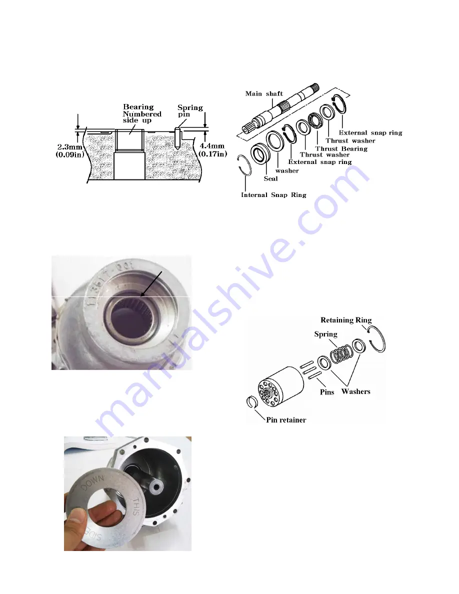
1. If the bearings were removed from the back
plate, a new one can be pressed in,Numbers
up,using the correct size bearing driver.
The back plate bearing should be pressed in
until 2.3
±
0.2 mm (0.09in
±
0.010in) is left
above the bore.
2. If spring pin that is used to position the
valve plate was removed or damaged,install
a new one.Allow the pin to protrude from
the back plate approximately 4.4mm(0.17 in)
Cam plate and shaft Installation
4.Apply some grease to the “THIS SIDE
DOWN” side of the cam washer before
installing into motor housing so it will stay in
place while installing rotating assembly.
5.Install the inside snap ring,thrust washer,and
thrust bearing on shaft.Install the outside
thrust washer and snap ring.
6.Install the shaft into the housing.Install the
washer and the new shaft seal.Secure them
with the retaining ring.
Rotating Unit Assembly and Installation:
1.If the piston block assembly was
disassembled complete the following.
Numbered end
3.The housing bearing should be pressed on
the numbered side,from the outside of the
housing inward.Until the numbered end is
recessed 2.0mm
±
0.3mm(0.078
±
0.015in)
in the housing bore.
disassembled complete the following.
If not , skip to step 10.
2.Install the three pins in oversize grooves in
spline end of piston block with the heads
facing inside of the block.
3.Install the pin retainer.
4.install the washers and spring.
5.Using same tools used to compress spring
during disassembly of block install washer,
spring,second washer,cap screw and nut in
the piston block.
6.Compress spring.
7.Install retaining ring.
8.Remove spring compression tools from the
piston block
4-36
Summary of Contents for T303HST
Page 18: ...3 Engine model Identification and serial number Location 1 16...
Page 21: ...MEMO 1 19...
Page 22: ...SECTION 3 GEAR TRAIN DIAGRAMS FIG 1 3 GEAR TRAIN DIAGRAM 1 20...
Page 24: ...MEMO 1 22...
Page 71: ...6 1 Hydrostatic system schematic 4 8...
Page 72: ...6 2 Hydrostatic system schematic 4 9...
Page 116: ...3 Rear transmission case 5 15 Fig 5 23...
Page 139: ...5 38 Fig 5 60...
Page 199: ...3 LINKAGE EXTERNAL 9 20 Fig 9 37 Linkage external...
Page 224: ...SECTION 6 WIRING DIAGRAM 10 14...


