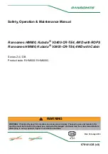
3) PTO CLUTCH
(3-1) DISASSEMBLY
1.Shaft,PTO clutch 2.Bearing ball(6203) 3.Collar(26x35x03) 4.Bearing ball
5.Gear,helical 35T 6.Bearing,ball 7.Clutch ass’y PTO
Fig.5-8
PTO BRAKE
5.Gear,helical 35T 6.Bearing,ball 7.Clutch ass’y PTO
Note:
Disassembly of the PTO clutch assembly should be done in a clean,dust-free place.Exercise special
attention to avoid damage of the seal rings,etc
a. Pull out PTO drive shaft rearwards.
b.Pull out PTO drive gear forwards.
c.Remove snap ring (D95 for hole),and take
bake-up plate,disc assembly,and driving
plates.
d.While holding return spring(43) compressed
with a special tool,remove snap ring
e. Disassemble into separate parts;piston,return
sparing,brake disc,and cover assembly.
(3.2) INSPECTION
a. Cover assembly
-Replace a cover assembly which has a damaged
or worn sliding surface.
-If there is any damage to the cover assembly
and the piston seal ring,these parts should also
be replaced.
b. Disc assembly
- If the thickness of a disc assembly exceeds the
usable limit mentioned below or combined width
of the disc assembly and driven plate is less than
23.8mm(0.937 in),replace both the disc
assembly and driven plate.
5-7
Fig.5-9
Summary of Contents for T303HST
Page 18: ...3 Engine model Identification and serial number Location 1 16...
Page 21: ...MEMO 1 19...
Page 22: ...SECTION 3 GEAR TRAIN DIAGRAMS FIG 1 3 GEAR TRAIN DIAGRAM 1 20...
Page 24: ...MEMO 1 22...
Page 71: ...6 1 Hydrostatic system schematic 4 8...
Page 72: ...6 2 Hydrostatic system schematic 4 9...
Page 116: ...3 Rear transmission case 5 15 Fig 5 23...
Page 139: ...5 38 Fig 5 60...
Page 199: ...3 LINKAGE EXTERNAL 9 20 Fig 9 37 Linkage external...
Page 224: ...SECTION 6 WIRING DIAGRAM 10 14...