720-0101
R. D. LD
01/26/15
Rev. 2
Page 3
Installation and Operation Instructions
A
2"
Figure 4
Figure 5
Figure 6
Figure 7
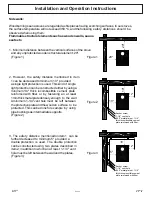
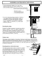
4. If the wall has been bedded in, a 2" vent hole
between the wall and the vertical surfaces of the
stove is enough. (Figure 4)
5. A 2-1/4" embedding with open sides at a minimum
1-1/4" distance away from the protected surface is
equivalent for a single light protection. Likewise,
a 4-1/4" embedding not touching the protected
surface would be equivalent for a double light
protection. (Figure 5)
Protecting the ceiling:
Provided the distance between the stove top and the
ceiling is minimum 47-3/4", no special protection is
needed for the ceiling. If the distance is less than 47-3/4",
you can choose one of the protection methods mentioned
in items 1-3. The ceiling protection must extend above the
vertical surfaces of the stove. (Figure 6)
Fireplace base:
The fireplace must be installed on a rigid base. This base must be strong enough to bear the
weight of the fireplace and to prevent any excessive rise of temperature of the structural
elements connected to it. When installing the stove on a wooden floor, it is advisable to use a
minimum 2" thick concrete slab or a minimum 1/4" thick fiber-reinforced cement plate
covered by a metal plate.
Protecting the floor in front of the stove:
The safety distances listed in items 1-5 cannot be applied
to a combustible floor area in front of the stove. This area
should be protected using a metal plate connected to the
floor and closely fitting the stove. The floor protection in
front of the stove must extend at least to 4" beyond
both sides of the oven mouth and to 15-3/4" in front of it.
Dimension A is determined according to the
protection method used for wooden surfaces
- 20" with no protection
- 10" with single light protection
- 5" with double light protection
15-3/4"
4-1/2"/ 2-1/4"
F
F in
No protection for the 47-1/4
ceiling
Single light
protection
35-1/2
4"
4"
15-3/4"
Concrete
Wood
15-3/4"

