background image

4


Qwik Install


STEP 1:


Choose a mounting location with 

good line of sight to the remote location. 

The supplied bracket can be mounted to a 

wall or to an existing pole up to 

2” 

diame-

ter. If only really short distances are need-

ed, the antenna can be mounted inside a 

building. 


TECH TIP:

 Microwaves travel in straight lines and they lose 

strength quickly when going thru buildings and trees. If there are 

objects in the microwave path, then useable distance will be reduced. If 

the target unit is less than 1 mile away then you won

t have to worry too 

much about a couple obstructions but if over 1 mile and there are some 

obstructions in the microwave path, then the performance will be re-

duced

.


2.4GHz is more forgiving than 5GHz.


STEP 2:


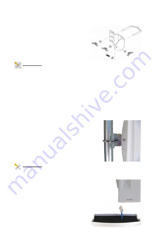
Mount the Bracket:


To mount to a wall: The supplied u

-

bolt is not used and the bracket is 

screwed directly to a wall using customer supplied screws. To mount to 

a pole: Use the supplied U

-

Bolt and wing nuts. Make sure to use a lock 

washer at each wing nut.     Tighten wing nuts evenly by hand. Use pli-

ers if additional tightness is needed.


STEP 3:


 Mount the antenna housing to the 

bracket. Put the hex head bolt thru the housing 

back fin. Put the star lock washer so it is be-

tween plastic housing and metal bracket. Install 

wing nut with lock washer. Adjust desired tilt an-

gle and tighten wing nut. Use pliers if additional 

tightness is needed.


TECH TIP:

 Because of the specially designed wide beamwidth an-

tenna, pointing is not critical and simply pointing in the general di-

rection of the receiving antenna will yield great results. 


STEP 4:


Remove the antenna bottom cover by using a 

coin or house key or screwdriver to push in one of the 

side snaps and then remove the cover.


STEP 5:


Route a CAT5/6 cable through the bottom cov-

er and plug into the RJ45 jack farthest 

from the LED

s. Keep the black gasket 

material in the bottom of the cover to help 

keep out dust and insects.


Summary of Contents for EZ-Go +

Page 1: ...igh Performance 802 11 Wireless Bridge Router Achieve up to 100 Mbit sec speed Link up to 3 miles with good line of sight Best security available WPA Field Proven Wireless Technology Now with TyconOS Firmware ...

Page 2: ...r than 20 feet to any power lines Safety For your own protection follow these safety rules Perform as many functions as possible on the ground Do not attempt to install the antenna on a rainy windy or snowy day or if there is ice or snow accumulation at the install site or if the site is wet Make sure there are no people pets etc below when you are working on a roof or ladder Watch out for any pow...

Page 3: ... above the number that says computer 192 168 1 87 is the IP address for the computer that opened the Discovery Tool To access the EZ Go your computer IP address must be on the same subnet ie 192 168 1 xxx In the example above 87 replaces xxx If your computer is not on the same subnet as the EZ Go unit you will either need to change the IP address of your computer or the EZ Go The unit ships from t...

Page 4: ... using customer supplied screws To mount to a pole Use the supplied U Bolt and wing nuts Make sure to use a lock washer at each wing nut Tighten wing nuts evenly by hand Use pli ers if additional tightness is needed STEP 3 Mount the antenna housing to the bracket Put the hex head bolt thru the housing back fin Put the star lock washer so it is be tween plastic housing and metal bracket Install win...

Page 5: ... from a single loca tion NOTE The device will usually go into a 1 2 minute reboot cycle when clicking on SAVE APPLY CHANGES During this time it will be unre sponsive The unit will beep once when it reboots and beep twice when it is ready 2 IP ADDRESS Default IP address for the EZ Go is 192 168 1 239 To access the EZ Go your computer IP address must be on the same subnet ie 192 168 1 xxx The EZ Go ...

Page 6: ...e at close range there is too much power and it has a tendency to overload the input stage of the units and perfor mance degrades The best performance will be seen with signal strength of 40 to 60dBm This signal strength can be viewed on the STATUS OVERVIEW page To change the Tx power go to NET WORK WIFI EDIT TRANSMIT POWER NOTE We recommend if changing power start by cutting it in half check sign...

Page 7: ...Antenna Beamwidth H V 35 deg 27 deg Antenna Front to Back 20dB 22dB Polarization MIMO MIMO PoE Specification Power Over Ethernet INPUT 100 240VAC 50 60Hz OUTPUT 24VDC 0 5A Average Power Consumption 4W Mechanical Specifications Color White Dimensions L x W x H 12 4 x 7 3 x 2 5 314 x 187x 65mm System Weight 7 lb 3 kg Ethernet Connector RJ45 Mount Pole up to 2 dia or Wall Environmental Specifications...

Page 8: ...s ready 9 CHANGING OPERATING MODE The EZ Go can be changed to an Access Point device on the NETWORK WIFI EDIT INTERFACE CONFIGURATION MODE page You might change a unit to AP if you wanted to use the unit as an access point talking to multiple clients We recommend using Access Point WDS and Station WDS in most cases to maintain the highest level of network transparency 10 AUTOMATIC REBOOT We highly...

Page 9: ...ssues can usually be helped by moving the antenna to a new location with better line of site If signal level is good between 35 and 75dBm try chang ing the wireless channel on the AP unit You should also do a site sur vey on both units to see what channels are already being used Select a channel that is not already used or one that has a very low signal strength If the signal level is too hot 30dB...

Page 10: ...een the PoE Inserter and antenna 6 PAINTING The EZ Go unit can be painted to match a particular house color Only non metallic enamel or latex paints should be used If a paint with metal content is used it will block the microwaves and cause reduced performance 7 COMMON MICROWAVE BARRIERS Tinted windows are made by applying a metallized film to the window If a window has tinting it will usually blo...

Page 11: ...the AP and the wireless encryption type that is being used B Associated Stations This section shows the stations that are communicating with this Access Point It provides information about the station MAC Address Network or ESSID Signal level being received from the station noise level negotiated TX and RX rates and Transmit CCQ TX CCQ which is a measure of signal quality good is 80 C System Secti...

Page 12: ...d total free memory If free memory is showing near zero you need to reboot the unit to clear memory E Network Section Shows information about the LAN and WAN interfaces The WAN interface is only active if the unit is configured as a router NOTES ...

Page 13: ...13 Explanation of LEDs and Connections NOTES ...

Page 14: ...receiving antenna Increase the separation between the equipment and receiver Connect the equipment into an outlet on a circuit different from that to which the receiver is connected Consult the dealer or an experienced radio TV technician for help FCC Caution Any changes or modifications not expressly ap proved by the party responsible for compliance could void the user s authority to operate this...

Page 15: ...all shipping charges incurred to ship the product to Tycon Systems Ty con Systems pays shipping charges to return the product to the origi nal purchaser For all other countries the original purchaser shall pay all shipping broker fees duties and taxes incurred in shipping products to and from Tycon Systems Provided the goods have not been modi fied or repair attempted by someone other than Tycon S...

Page 16: ...16 8000004 Rev12 EZ Go LT Qwik Install Guide NOTES ...

Reviews: